
Manually guided blower

a blower and guide technology, applied in the direction of machines/engines, cleaning equipment, turf growing, etc., can solve the problems of inability to operate and inability to attach to the discharge opening, and achieve the effect of low number of components

Active Publication Date: 2008-06-05
ANDREAS STIHL AG & CO KG
View PDF2 Cites 36 Cited by
  • Summary
  • Abstract
  • Description
  • Claims
  • Application Information

AI Technical Summary

Benefits of technology

[0023]A switch is advantageously provided for the component or attachment at the discharge opening. As a result, operation without an attachment at the discharge opening is not possible. The attachment at the discharge opening can be exchanged or replaced without also having to remove or disassemble an attachment at the intake opening. This facilitates handling and conversion.
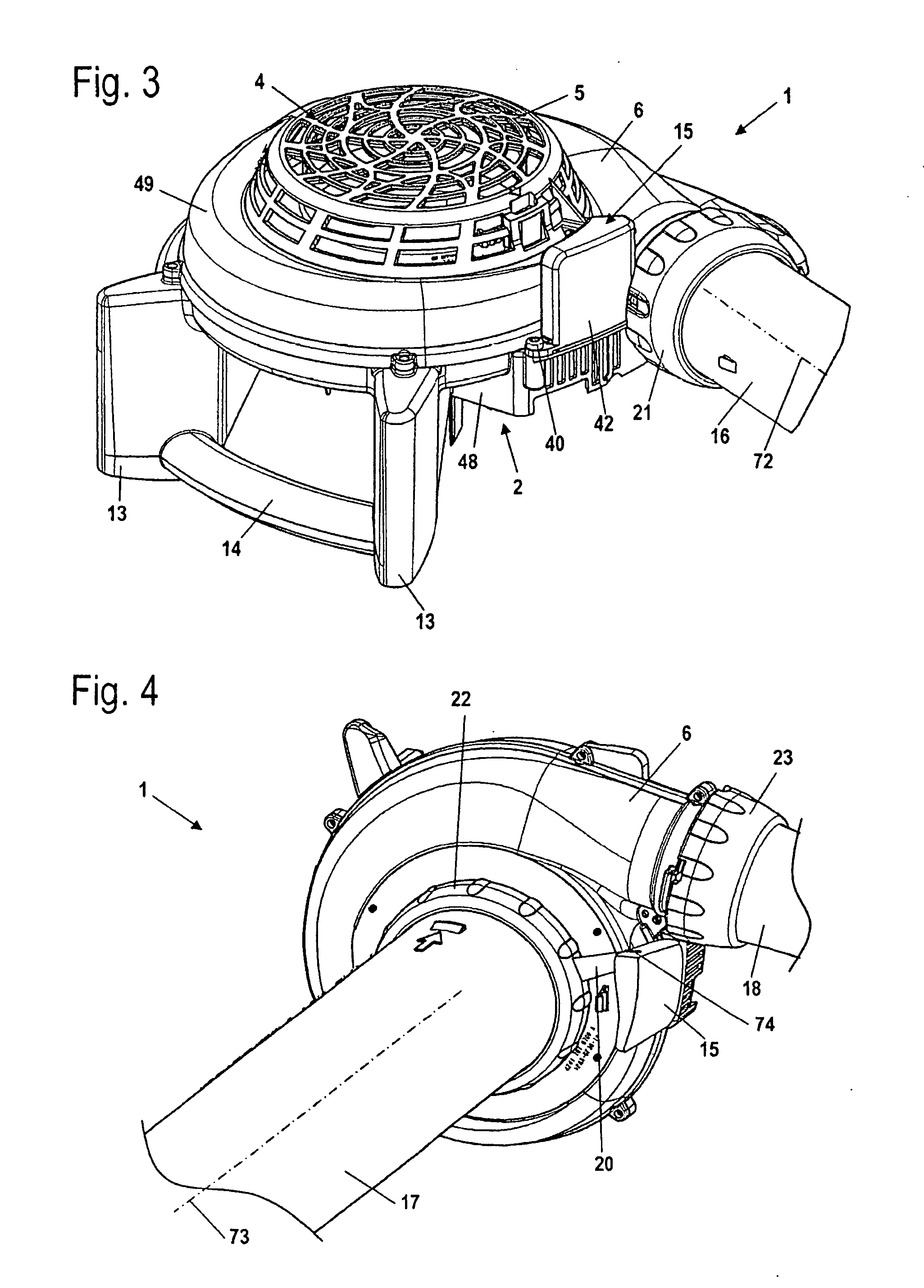
[0034]At least one attachment can be connected to the housing via a rotation of a securement element of the attachment about an axis of rotation that extends transverse to the opening. The securement element of the attachment can be monolithically formed with the attachment and can, for example, be provided with a thread or elements of a bayonet closure. The attachment advantageously has an actuating element for the actuation of the switch. The actuating element is advantageously an actuating arm that in particular extends outwardly relative to the axis of rotation; the actuating arm actuates the switch when the attachment is secured to the opening. As a result, in a straightforward manner it is possible to achieve actuation of the switch when the attachment is secured to the opening. A straightforward configuration is provided if both of the switches are disposed in a single or common switch housing, and the switch housing has a support, on which the switches are held, as well as a cover, which is connected with the support via at least one latching or snap mechanism. This results in a simple, compact construction. The switches can also be provided on existing blowers at a later stage.

Problems solved by technology

As a result, operation without an attachment at the discharge opening is not possible.
In this connection, the switches are actuated only if the attachment is correctly held, so that operation is also not possible when the attachments are incorrectly fixed.

Method used


Image

  • Manually guided blower
  • Manually guided blower
  • Manually guided blower

Examples


Embodiment Construction

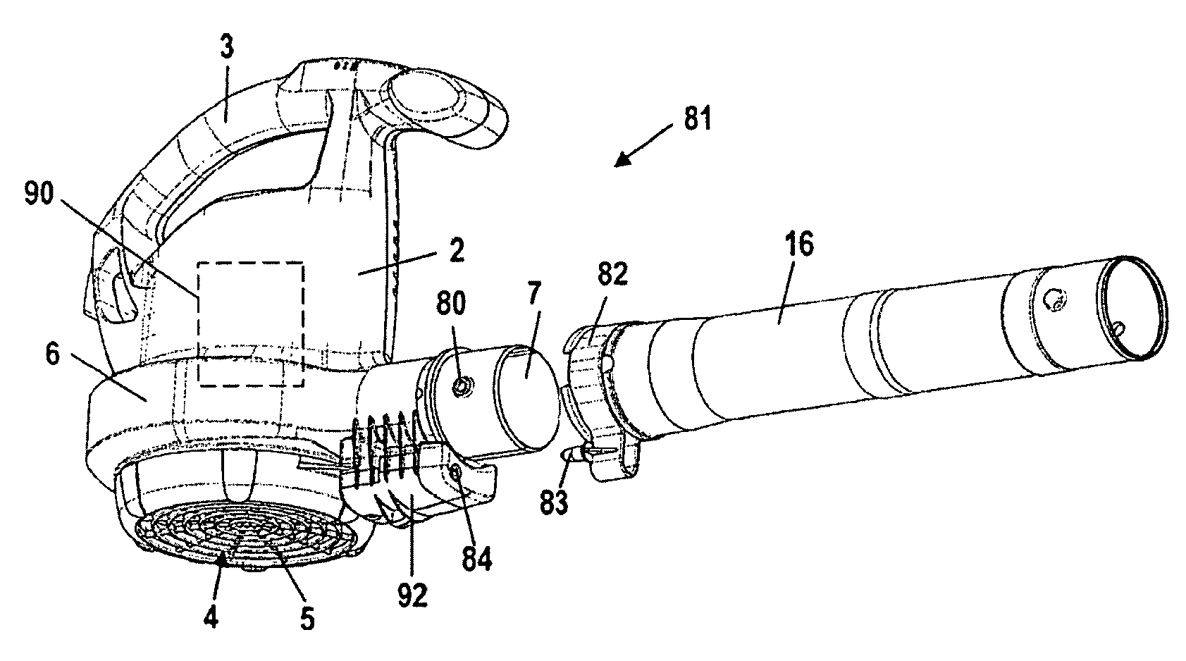
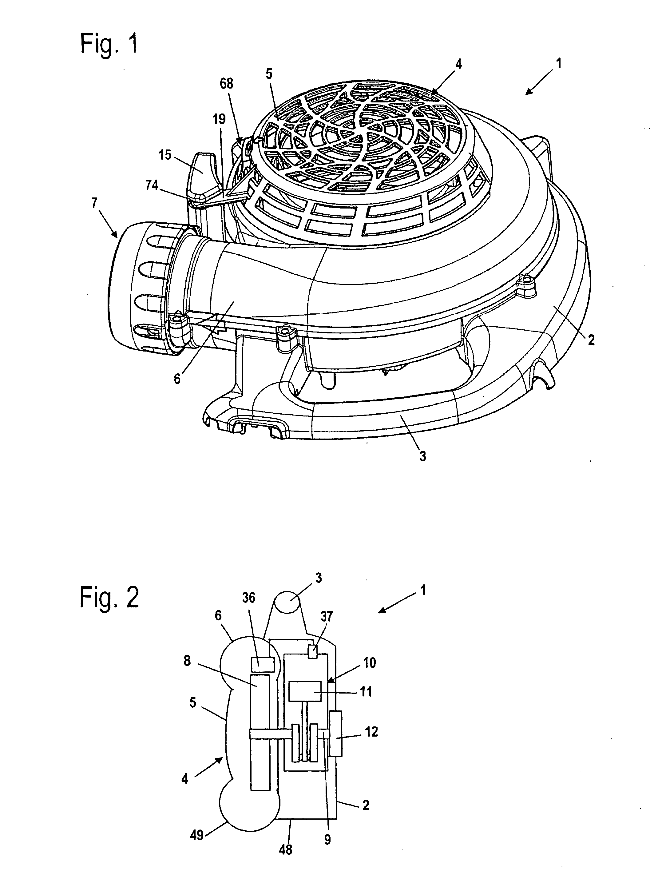
[0036]Referring now to the drawings in detail, the blower 1 shown in FIG. 1 has a housing 2 to which is secured a first handle 3. The blower 1 has a blower spiral or volute 6 that conveys an air stream through a discharge opening 7. The air stream is drawn in via an intake opening 4, which is covered by an intake grille 5.

[0037]FIG. 2 schematically shows the construction of the blower 1. The housing 2 includes an engine housing 48, in which is disposed an internal combustion engine 10, as well as a blower housing 49, which includes the blower spiral 6. The internal combustion engine 10 has a piston 11 that rotatably drives a crankshaft 9. A schematically illustrated starter device 12 is provided for starting the internal combustion engine 10. The crankshaft 9 extends into the blower housing 49. Disposed at that end of the crankshaft 9 that extends into the blower housing 49 is an impeller 8 that draws the air stream in via the intake opening 4 and conveys the air stream through the ...


PUM


Abstract

A manually guided blower having a housing in which is disposed a drive motor that rotatingly drives an impeller. The impeller draws in an air stream via an intake opening and conveys the air stream through a discharge opening of the housing. The blower has at least one attachment that can be detachably connected to the housing in the region of one of the openings. The blower has at least one switch that is actuated when the attachment is secured to the opening, whereby the drive motor is in a ready-to-operate state only when the switch is actuated.

Description

[0001]The instant application should be granted the priority date of 5 Dec. 2006, the filing date of the corresponding German patent application DE 10 2006 057 184.3.BACKGROUND OF THE INVENTION[0002]The present invention relates to a manually guided or portable blower.[0003]U.S. Pat. No. 6,442,790 discloses a blower having an intake opening and a discharge opening. An intake grille or a suction tube can be secured to the intake opening, and a discharge tube or a collection bag can be disposed at the discharge opening. Thus, the blower can be used both in blower operation as well in suction operation, for example to collect yard material such as leaves or the like. The blower known from U.S. Pat. No. 6,442,790 is operated with an electric motor. The intake grille or the suction tube is attached to the discharge tube and is fixed on the housing. A switch is provided that is actuated by the installed intake grille. In order to be able to exchange the attachment at the discharge opening...

Claims


Application Information

Patent Timeline
IPC IPC(8): E01H1/08A47L5/14F02B63/00
CPCA01G1/125A47L5/14A47L5/225E01H1/0809A47L9/2842A47L9/2857A47L9/2889A47L5/24A01G20/47
Inventor KREMSLER, DIETERDAWEN, ROMANLANGHANS, KLAUSRABIS, MANFREDSCHELLIN, KIRSTEN
Owner ANDREAS STIHL AG & CO KG
Learn More