Fine water mist multiple orientation discharge fire extinguisher

a fire extinguisher and fine water mist technology, applied in fire rescue, medical science, dental surgery, etc., can solve problems such as loss of fire protection, and achieve the effects of facilitating the generation of fine water mist droplets, reducing weight, and simplifying mounting

Active Publication Date: 2008-06-05
ADA TECH +1
View PDF18 Cites 62 Cited by
  • Summary
  • Abstract
  • Description
  • Claims
  • Application Information

AI Technical Summary

Benefits of technology

[0021]The present invention can provide a number of advantages depending on the particular configuration. By way of example, the suppression system can be a portable fire extinguisher UDOS (Universal Discharge Orientation System) that can extinguish fires aboard space-craft in low gravity or microgravity environments or in vehicles, even when the vehicle is upside down. The suppression system is preferably a water mist system that can operate in microgravity, in any gravitational field, or at any orientation. The UDOS can have many desirable features, including a low weight and a totally self-contained and modular design. There commonly is no complex piping to thread through a crowded habitation module and mounting is simplified. A perforated flow tube containing multiple holes allows the liquid to enter the tube from anywhere in the contained liquid volume. This is desirable, since segments of the separation member can be forced against a single opening with the suppression liquid (e.g., water) still remaining in the volume during discharge. Use of a perforated tube allows water to flow almost anywhere within the bladder and still exit via the perforated tube. The separation member separates the water and gas constituents but can still allow the pressure in the gas phase to be successfully transferred to the water / liquid phase to discharge the contents and facilitate the generation of fine water mist droplets. This can remove the gravity requirement of a typical fire extinguisher, which suffers operational problems when discharged on its side. The system can exploit the slow pressure decay of the gas phase during discharge to force the flow of water / liquid from the containment vessel and allow the system contents to be depleted effectively in all orientations. This type of system can be deployed in aircraft, spacecraft, and other vehicles without concern for system orientation with respect to gravity. The system can use a check valve and aspirating venturi to blend the liquid with the propellant / atomization gas. The body housing the venturi can be configured to use minimal turns and length of flow path from inlet to outlet. This keeps the gas and liquid phases well-mixed in the flow. The generation of fine water mist can be enhanced by the presence of a uniform distribution of small bubbles of gas in a continuous flow of water.

Problems solved by technology

While each of these technologies is effective, they also have drawbacks.
Although halon deployed in low earth orbit (LEO) or farther out will not come into contact with the Earth's ozone layer, NASA protocols require de-orbiting of a spacecraft after deployment of a halon extinguisher because the ECLSS systems have no means of scrubbing bromofluorocarbons.
Another issue is the loss of fire protection once the halon system has been discharged.

Method used


Image

  • Fine water mist multiple orientation discharge fire extinguisher
  • Fine water mist multiple orientation discharge fire extinguisher
  • Fine water mist multiple orientation discharge fire extinguisher

Examples


first embodiment

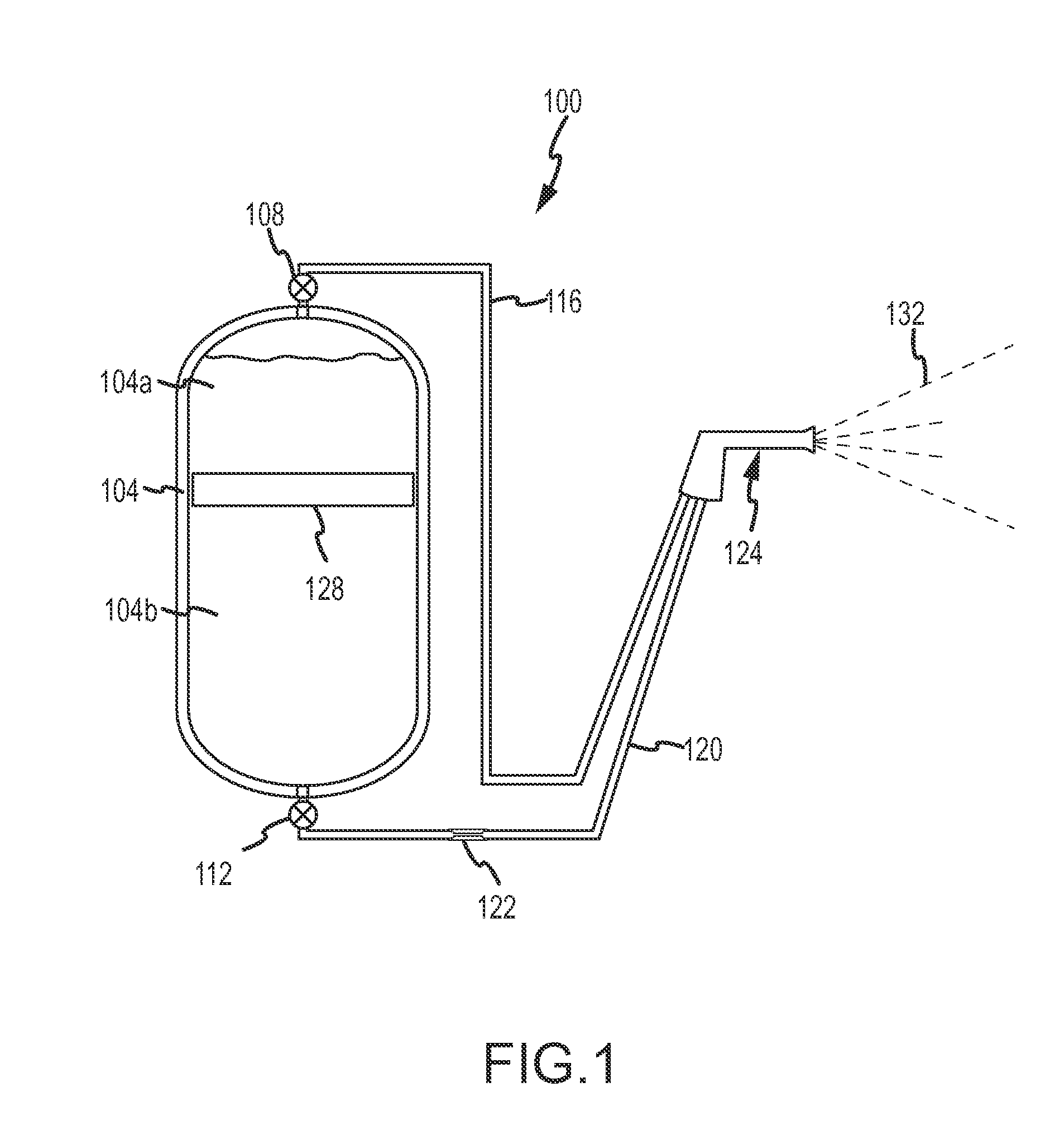
[0040]FIG. 1 depicts an extinguisher 100 according to a The extinguisher 100 includes a containment vessel 104, first and second valves 108 and 112, respectively, first and second flexible hoses 116 and 120, pressure control 122 (optional) (which controls the liquid pressure in the second hose 120), and a hand-held nozzle assembly 124. The containment vessel 104 is rigid and pressure resistant and includes a movable (rigid) piston 128 positioned between upper and lower portions 104a and b of the vessel 104. The upper portion 104a of the vessel includes a carrier gas while the lower portion 104b includes a suppression liquid; therefore, the piston spatially defines the liquid / gas interface.

[0041]The first and second valves 108 and 112 are closed when the extinguisher is not in operation and opened when in operation. When the valves are opened, the pressure of the gas and gravity cause the piston to move downwardly, expelling liquid through the hose 120. To make this possible, the ga...

second embodiment

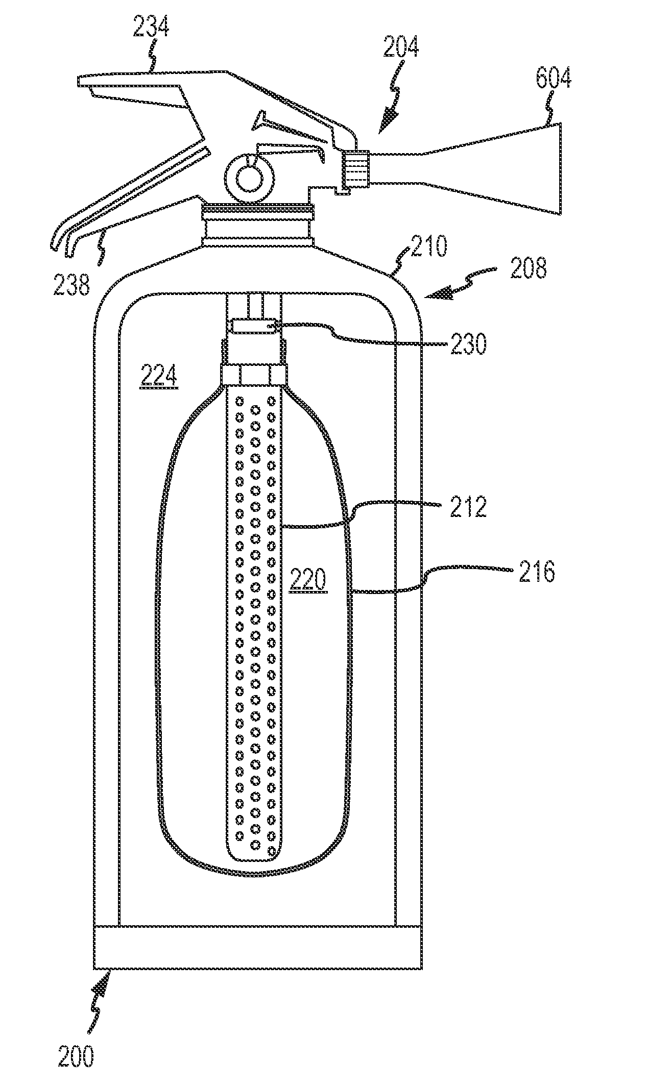
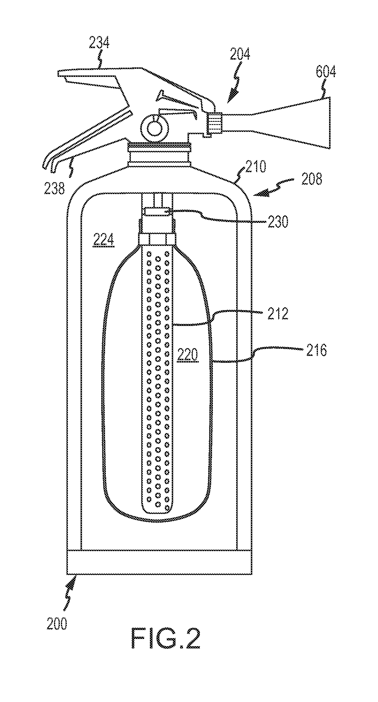
[0055]An extinguisher is shown in FIG. 2.

[0056]The extinguisher 200 includes a nozzle assembly 204 and a containment vessel assembly 208. The vessel assembly 208 includes a containment vessel 210, a perforated flow tube 212, and an elastomeric membrane or bladder 216 surrounding and enclosing fully the flow tube 212. The membrane 216 divides the inner volume of the vessel 210 into a first (inner) region 220 containing the suppression liquid and a second (outer) region 224 containing the carrier gas.

[0057]The vessel assembly 208 can include a piston valve 230 to actuate liquid and gas flow through the upper portion of the tube 212, and the nozzle assembly a mixing and atomization device (not shown) in communication with the tube 212 and located at the top of the tank. The piston valve is actuated by movement of one or both of the handles 234 and 238.

[0058]The bladder can be any elastic and / or elastomeric material. Preferably, the bladder has a durometer between about 75 Shore 00 to ...

third embodiment

[0072]The operation of the extinguisher of the third embodiment will now be discussed with reference to FIGS. 2-8.

[0073]An operator activates the extinguisher by gripping and squeezing the upper and lower handles 612 and 616 to move the upper handle towards the lower handle. In response, the bearing member 624 displaces the manual release valve 628 inwardly along the first passageway 400, bringing the ports 500a-d into fluid communication with the annulus 504. When not in operation, the liquid flows through the tube 212 and into the second passageway 404. Liquid flow into the third passageway 408 is blocked by the closed check valve 720 and flow through the proximal portions 532 and 536 of the first passageway is blocked by the valve portion 420. This is so because the ports are not in fluid communication with the annulus 504. When the valve 628 is displaced inwardly along the first passageway, the ports 500a-d move into the annulus 504. This displacement into the annulus 504 effect...


PUM


Abstract

The present invention is directed to a suppression system in which a carrier gas and suppression liquid are contained in a common containment vessel and separated by a separation member. The separation is one or more of movable, deformable, or shape changing in response to pressure exerted by the stored gas.

Description

CROSS REFERENCE TO RELATED APPLICATION[0001]The present application claims the benefits of U.S. Provisional Application Ser. No. 60 / 862,383, filed Oct. 20, 2006, of the same title, which is incorporated herein by this reference in its entirety.STATEMENT REGARDING FEDERALLY SPONSORED RESEARCH OR DEVELOPMENT[0002]The U.S. Government has a paid-up license in this invention and the right in limited circumstances to require the patent owner to license others on reasonable terms as provided for by the terms of Contract No. NNC06CA80C awarded by the National Aeronautics and Space Administration.FIELD OF THE INVENTION[0003]The invention relates generally to suppression of exothermic reactions and particularly to suppression of fires.BACKGROUND OF THE INVENTION[0004]Having an effective and reliable strategy for fire safety is of the utmost importance, particularly in isolated and enclosed environments, such as in terrestrial vehicles and aircraft, and partial-gravity conditions, such as in s...

Claims


Application Information

Patent Timeline
Patent Type & Authority Applications(United States)
IPC IPC(8): A62C3/00
CPCA62C3/08A62C35/023A62C31/02
Inventor BUTZ, JAMES R.TURCHI, CRAIG S.KIMBALL, AMANDAMCKINNON, THOMASRIEDEL, EDWARD P.
Owner ADA TECH
Why Eureka
Try Eureka