Electrochemical gas sensor chip and method of manufacturing the same

a gas sensor and electrochemical technology, applied in the direction of instruments, vacuum evaporation coatings, coatings, etc., can solve the problems of increasing the operation temperature, not suitable for portable devices, and still facing the limitations of sensors for use in portable devices

Inactive Publication Date: 2008-06-05
ELECTRONICS & TELECOMM RES INST +1
View PDF9 Cites 32 Cited by
  • Summary
  • Abstract
  • Description
  • Claims
  • Application Information

AI Technical Summary

Problems solved by technology

Although a semiconductor gas sensor using a conductivity change in an oxide semiconductor by contact between an oxidative gas and a reductive gas is commercially produced, the sensor still faces technical limitations for use in portable devices when a heater consumes a large amount of power, which raises operation temperature of the oxide semiconductor to sense a gas.
Also, an optical gas sensor determining the kind of gas by a change in an ultraviolet (UV) spectrum passing through sensing gas is commercially produced, but it is still not suitable for use in portable devices because a UV source or detector is difficult to downsize, power consumption is high, and the sensor is also difficult to downsize due to a long optical path needed to increase sensitivity.
Compared with a semiconductor or optical sensor, the conventional electrochemical gas sensor is difficult to equip in a portable device, such as a mobile phone, due to the sensor's size and stability and because it is operated in room temperature.
Furthermore, although the conventional electrochemical gas sensor does not need a light source, and thus consumes less power than a semiconductor or optical sensor, it contains a liquid electrolyte, and thus is large and unstable due to its acidity.
Although this structure has electrodes at both sides of the polymer layer having excellent proton conductivity, so it may be made somewhat smaller, it may not be made into a chip to be integrated with a driving circuit.
However, the current gas sensor may not be integrated on one board together with other elements, which are necessary to be driven, so a sensor chip has to be developed to solve this problem.
However, in an electrochemical gas sensor having this structure, proton conductivity of an electrolyte may be changed according to a concentration of surrounding moisture, so an actual concentration of sensed gas may be erroneously sensed.

Method used


Image

  • Electrochemical gas sensor chip and method of manufacturing the same
  • Electrochemical gas sensor chip and method of manufacturing the same
  • Electrochemical gas sensor chip and method of manufacturing the same

Examples


Embodiment Construction

[0028]Hereinafter, the present invention will be described in detail with reference to drawings illustrating exemplary embodiments of the present invention.

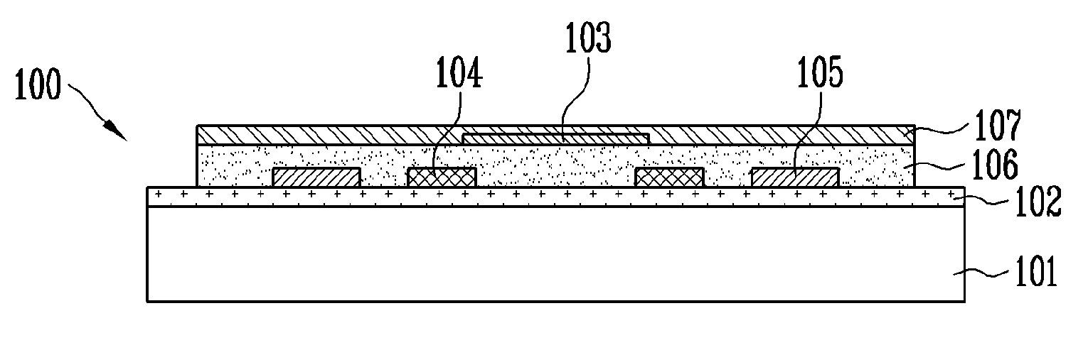
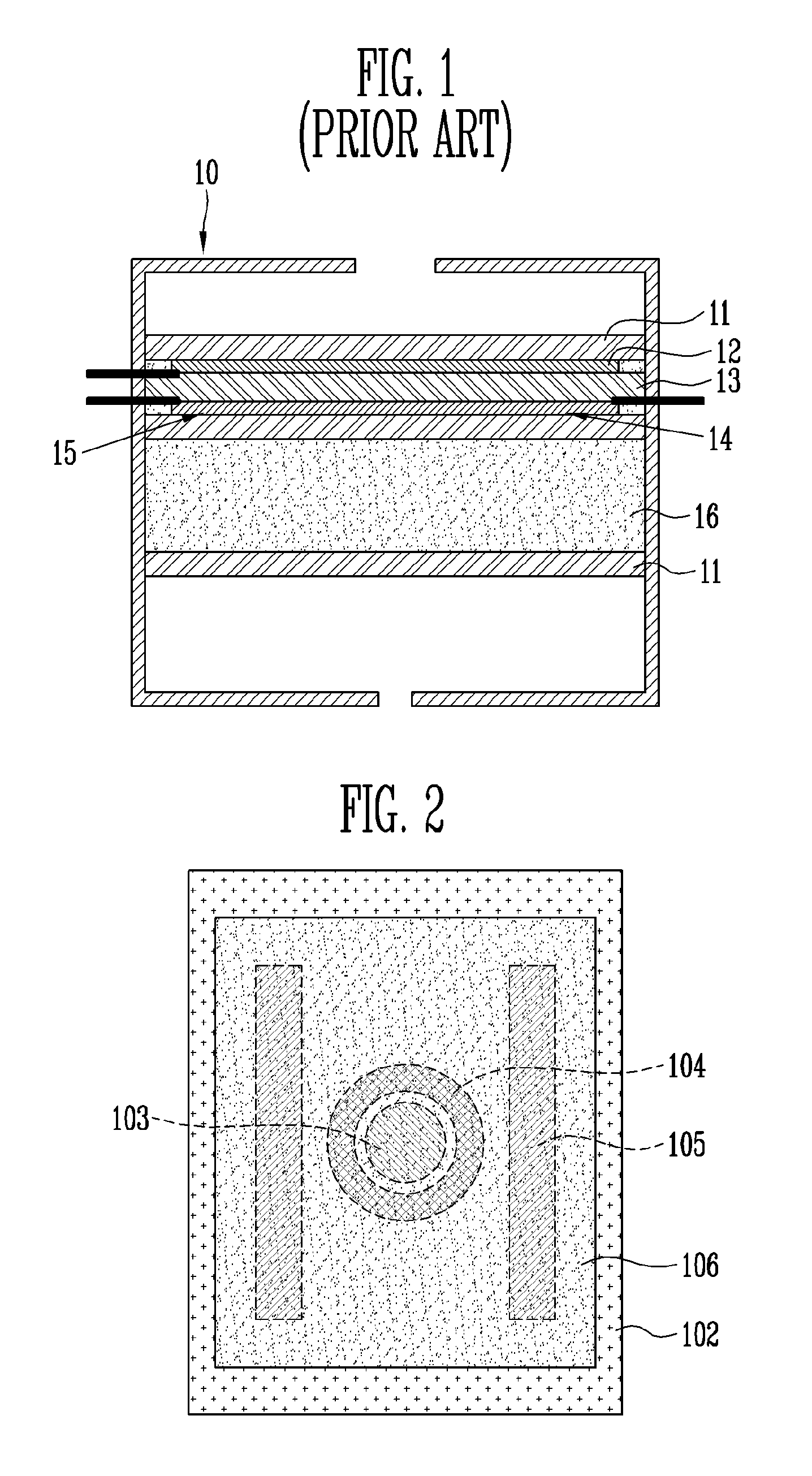
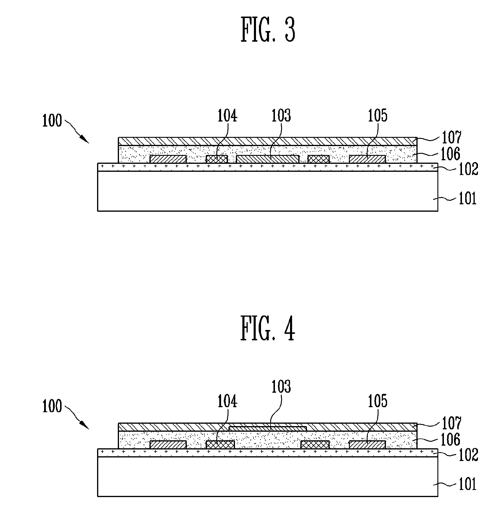
[0029]FIGS. 2 and 3 are a plan view and a cross-sectional view of an electrochemical gas sensor chip using a solid electrolyte according to an exemplary embodiment of the present invention, respectively, and FIG. 4 is a cross-sectional view of an electrochemical gas sensor chip using a solid electrolyte according to another exemplary embodiment of the present invention.

[0030]Referring to FIGS. 2 and 3, an electrochemical gas sensor chip 100 according to an exemplary embodiment of the present invention includes a substrate 101, an insulating layer 102 formed thereon, a working electrode 103 patterned on the insulating layer 102, a counter electrode 104 and a reference electrode 105, a solid electrolyte layer 106 formed on the patterned electrode, and a hydrophobic microporous membrane 107.

[0031]The substrate 101, as a base on whic...


PUM

PropertyMeasurementUnit
proton conductivityaaaaaaaaaa
hydrophobicaaaaaaaaaa
conductiveaaaaaaaaaa

Abstract

An electrochemical gas sensor and a method of manufacturing the same are provided. The electrochemical gas sensor includes: a substrate; an electrode patterned on the substrate; a solid electrolyte layer having proton conductivity formed on the substrate having the patterned electrode; and a hydrophobic microporous membrane formed on the solid electrolyte layer. The gas sensor chip is easily integrated with a driving circuit and uses a solid electrolyte layer, and thus it can be manufactured in a smaller size and in a large area process.

Description

CROSS-REFERENCE TO RELATED APPLICATION[0001]This application claims priority to and the benefit of Korean Patent Application No. 2006-121377, filed Dec. 4, 2006, and No. 2007-59266, filed Jun. 18, 2007, the disclosure of which is incorporated herein by reference in its entirety.BACKGROUND[0002]1. Field of the Invention[0003]The present invention relates to an electrochemical gas sensor chip and a method of manufacturing the same, and more particularly, to an electrochemical gas sensor chip using a solid electrolyte, and a method of manufacturing the same.[0004]This work was supported by the IT R&D program of Ministry of Information and Communication / Institute for Information Technology Advancement [2006-S-006-01, Components / Module technology for Ubiquitous Terminals.][0005]2. Discussion of Related Art[0006]Gas sensors have been applied to various applications such as the automobile industry, the environmental industry, the food and beverage industry, the robotics industry, etc., and...

Claims


Application Information

Patent Timeline
Patent Type & Authority Applications(United States)
IPC IPC(8): G01N27/407C23C14/24C23C14/34
CPCG01N27/4045
Inventor MOON, SEUNG EONKIM, EUN KYOUNGLEE, HONG YEOLPARK, JONG HYURKPARK, KANG HOKIM, JONG DAEMIN, SEOK HONGJUNG, BYUNG GILHA, SEUNG CHUL
Owner ELECTRONICS & TELECOMM RES INST
Why Eureka
Try Eureka