Permanent magnet electrical rotating machine, wind power generating system, and a method of magnetizing a permanent magnet

a permanent magnet and rotating machine technology, applied in the direction of magnetic bodies, magnetic circuit shapes/forms/constructions, greenhouse gas reduction, etc., to achieve the effect of reducing the size and reducing the cost of the structur

Active Publication Date: 2008-06-05
HITACHI IND PROD LTD
View PDF20 Cites 43 Cited by
  • Summary
  • Abstract
  • Description
  • Claims
  • Application Information

AI Technical Summary

Benefits of technology

[0012]The present invention provides a permanent magnet electrical rotating machine enable to be read

Problems solved by technology

However, the patent document 1 does not describe

Method used


Image

  • Permanent magnet electrical rotating machine, wind power generating system, and a method of magnetizing a permanent magnet
  • Permanent magnet electrical rotating machine, wind power generating system, and a method of magnetizing a permanent magnet
  • Permanent magnet electrical rotating machine, wind power generating system, and a method of magnetizing a permanent magnet

Examples


first embodiment

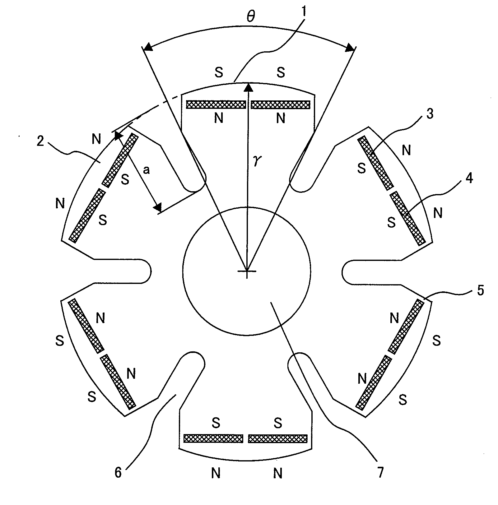
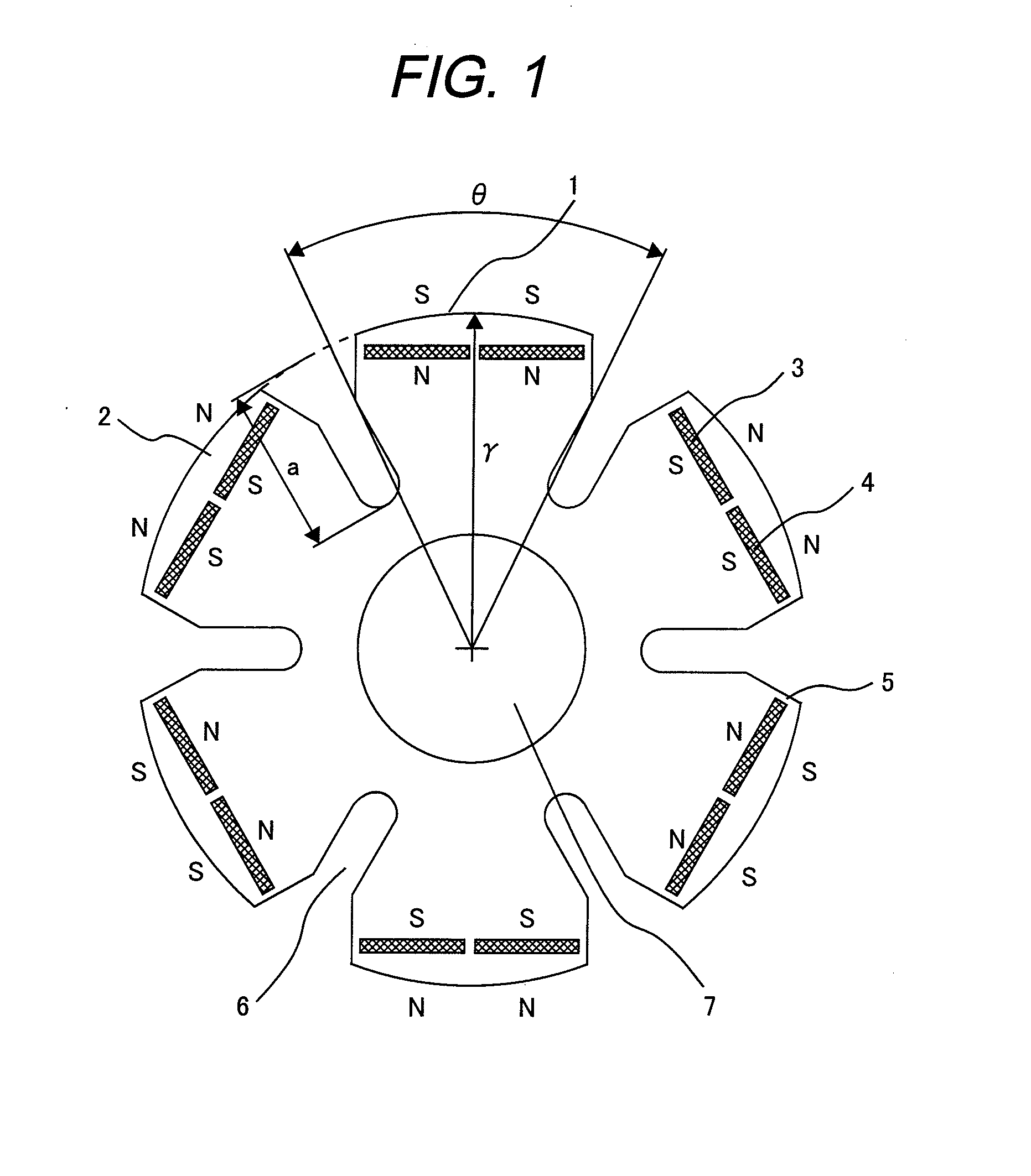
[0032]FIG. 1 is a cross-sectional view showing an end of a permanent magnet rotor of a six-pole permanent magnet electrical rotating machine in a first embodiment of the present invention. The permanent magnet rotor 1 comprises a rotor iron core 2, permanent magnets 3 and 4 being seated in permanent magnet slots 5 formed in the rotor iron core 2. Two permanent magnets 3 and 4 are provided for each pole. The rotor iron core 2 has a radius r and each pole of the rotor iron core 2 in radial direction has end with the angle θ.

[0033]The permanent magnet rotor 1 also has a cooling airflow channel 6 between poles through which cooling air is made to flow to efficiently cool the inside of an electrical power generator. As shown in FIG. 1, the cooling airflow channel 6 has a groove formed an approximately trapezoidal shape on the outer periphery side of the rotor iron core 2, which extends from an outer end side in a radial direction of the approximately trapezoidal shape to a radial center....

second embodiment

[0039]FIG. 4 is a cross-sectional view showing an end of a permanent magnet rotor of a six-pole permanent magnet electrical rotating machine in a second embodiment of the present invention. As in the first embodiment, a permanent magnet rotor 20 comprises a rotor iron core 21, permanent magnets 3 and 4 being seated in permanent magnet slots 5 formed in the rotor iron core 21. Two permanent magnets are provided for each pole. The permanent magnet rotor 20 also has a cooling airflow channel 6 between poles through which cooling air is made to flow to efficiently cool the inside of the electrical power generator. An airflow cooling axial duct 8 is provided for each pole inside the permanent magnets 3 and 4 in the rotor iron core 21 toward the axial direction; cooling air can be made to flow through the airflow cooling axial duct 8 as well. The rotor iron core 21 is connected to the shaft 7. Although, in FIG. 4, the airflow cooling axial duct 8 is provided only at a single location for ...

third embodiment

[0047]FIG. 14 shows one pole of the permanent magnet rotor of the permanent magnet electrical rotating machine in a third embodiment of the present invention. The rotor iron cores 2 and 21 in the first and second embodiments are changed to a rotor iron core 22 in the third embodiment as shown in FIG. 14, in which the outer periphery of the rotor iron core 22 is not concentric with the inner periphery of the stator 17, and the outer periphery is symmetrical with respect to the center of the periphery for the one pole, so that the waveform of an induced voltage can be readily converted into a sine wave.

[0048]That is, in this embodiment in FIG. 14, Gap 1=Gap 2, Gap 1>Gap 3.

[0049]FIG. 15 shows one pole of the permanent magnet rotor of the permanent magnet electrical rotating machine in the third embodiment of the present invention. The rotor iron cores 2 and 21 in the first and second embodiments are changed to a rotor iron core 23 in the third embodiment as shown in FIG. 15, in which t...


PUM


Abstract

A permanent magnet electrical rotating machine having a permanent magnet rotor and a stator, wherein:
    • a plurality of permanent magnets are disposed in a rotor iron core of the permanent magnet rotor along a periphery of the rotor iron core, polarities thereof being alternately changed;
    • a cooling airflow channel is formed between each pair of adjacent opposite poles on the rotor iron core; and the cooling airflow channel has an approximately trapezoidal shape on an outer periphery side of the rotor iron core; and extends from an end on a central side in a radial direction of the approximately trapezoidal shape to a radial center.

Description

CLAIM OF PRIORITY[0001]The present application claims priority from Japanese application serial No. 2006-316444, filed on Nov. 24, 2006, the content of which is hereby incorporated by reference into this application.BACKGROUND OF THE INVENTION[0002]1. Field of the Invention[0003]The present invention relates to a permanent magnet electrical rotating machine, a wind power generating system, and a method of magnetizing a permanent magnet.[0004]2. Prior Art[0005]The amount of electricity produced by wind power has greatly increased in recent years. There have been increasing demands for permanent magnet-type machines with a large capacity of 1 MW or more to improve the economy by increasing the capacity of a single machine. Although the efficiency of a large-capacity permanent magnet-type machine is high, the value of its loss is large. When the body of an electrical rotating machine is enlarged so as to suppress the heat generation density to a level nearly equal to that of a small-ca...

Claims


Application Information

Patent Timeline
IPC IPC(8): H02K21/00H02K9/02H01F13/00
CPCH02K1/223H02K1/276H02K7/1838H02K1/325H02K2213/03H02K1/2766Y02E10/74H02K1/27F03D3/00
Inventor KORI, DAISUKEFUJIGAKI, TETSUOAIZAWA, SHUJIIIZUKA, MOTONOBUIWAI, YASUSHIMIKAMI, HIROYUKIKIMURA, MAMORU
Owner HITACHI IND PROD LTD
Why Eureka
Try Eureka