Piezoelectric generators for munitions fuzing and the like

a technology of munitions fuzing and generators, applied in the direction of generators/motors, electric fuzes, ammunition fuzes, etc., can solve the problems of requiring the allocation of valuable space, not cost-effective use of reserve batteries for such low power requirements, and affecting the safety of personnel

Active Publication Date: 2008-06-05
OMNITEK PARTNERS LLC
View PDF7 Cites 11 Cited by
  • Summary
  • Abstract
  • Description
  • Claims
  • Application Information

AI Technical Summary

Benefits of technology

[0009]An objective of the present invention is to provide new methods for the development of devices that would allow firing acceleration and or other similar impact force induced charges generated in piezoelectric elements to be sustained for periods of times that are significantly longer than the duration of the firing acceleration or other similar impact forces.

Problems solved by technology

The use of reserve batteries for such very low power requirements is not cost effective and requires the allocation of valuable space and may face safety issues.
Current applications of piezoelectric elements of various designs and configurations such as stacks of piezoelectric ceramic, film layers, etc., which are loaded (strained) due to the firing acceleration in the axial direction, in bending, etc., and which may be equipped with appropriate inertial components to increase the generated loads (axial, bending, torsional, etc.), or are equipped with motion amplifying mechanisms to amplify the applied stains, have a common shortcoming that reduces their effectiveness as electrical energy generators and prevents efficient collection and storage of the generated charges.
As a result, the window for extraction and storage of the generated electrical charge is equally small, making efficient harvesting of the generated charge very difficult.

Method used


Image

  • Piezoelectric generators for munitions fuzing and the like
  • Piezoelectric generators for munitions fuzing and the like
  • Piezoelectric generators for munitions fuzing and the like

Examples


embodiment 50

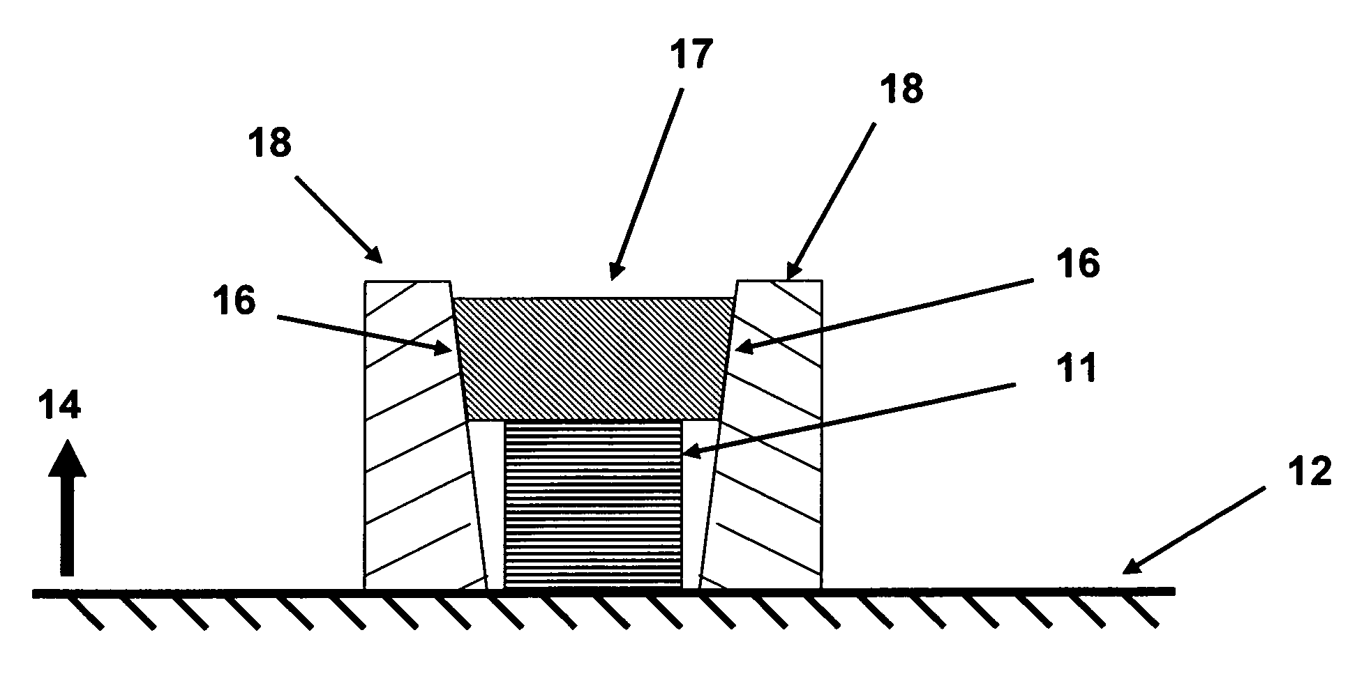
[0052]In general, the position of the traveling wedging element(s) may be exchanged. For example, in the embodiment of FIG. 6, the piezoelectric stack 41 (51 in FIG. 7) and its two sides wedging elements 44 (52 in FIG. 7) may be set against the munitions structure 12 as shown in FIG. 7. In this embodiment 50, the supports 42 (53 in FIG. 7) are then joined together by the relatively rigid backing 54, and positioned as shown in FIG. 7 over the piezoelectric stack assembly. The piezoelectric stack is held against the munitions structure surface 12, but is allowed to expand and / or contract. As the munitions is fired, the acceleration of the munitions in the direction of the arrow 14 would act on the mass of the assembly of the elements 53 and the backing 54, thereby applying a compressive force on the piezoelectric stack 51 via the side wedges 52. With an appropriate wedging angle of the surfaces 55, the assembly of the piezoelectric stack 51 and the blocks 52 is locked in place relativ...

embodiment 60

[0054]It is noted that even though in the embodiments shown in FIGS. 2-7 the piezoelectric layers are stacked in planes perpendicular to the direction of the applied compressive loads, the compressive loads may be applied to similar layers stacked in numerous other configurations. For example, in one embodiment 60, the layers 66 may be stacked to form a cone segment 61, which can have an inside hole 62 as shown in the schematic of longitudinal cross-sectional view in FIG. 8a (shown with ring 63). The layers are shown in the top view of piezoelectric element 61 in FIG. 8b (without ring 63). The cone angle is indicated as 65. A ring 63 with a matching inside cone angle is used as the support element attached to the munitions structure 12. During the firing, the firing acceleration in the direction 14 acts on the mass of the piezoelectric element 61, thereby wedging it inside the ring 63. An additional mass 64 may be used to increase the generated compressive force. With an appropriate...


PUM


Abstract

A method for generating power from acceleration of a device is provided. The method including: applying a force to a piezoelectric member due to the acceleration; and sustaining a strain in the piezoelectric member resulting from the applied force so as to increase a time of power output from the piezoelectric member. The device can be a munition.

Description

CROSS-REFERENCE TO RELATED APPLICATION[0001]This application claims the benefit of provisional application Ser. No. 60 / 872,248 filed on Dec. 2, 2006, the contents of which is incorporated herein by reference.BACKGROUND OF THE INVENTION[0002]1. Field of the Invention[0003]The present invention relates generally to piezoelectric generators and, more particularly, to piezoelectric generators for munitions fuzing.[0004]2. Prior Art[0005]All existing and future smart and guided gun-fired munitions and mortars that are equipped with electronics for fuzing or other similar purposes require electric power for their operation. The amount of power required for proper operation of certain components in gun-fired munitions, for example for the operation of certain fuzing electronics, is small enough to be provided by harvesting the electric charge generated directly from piezoelectric elements due to the firing acceleration induced straining. The advantage of using piezoelectric elements that c...

Claims


Application Information

Patent Timeline
Patent Type & Authority Applications(United States)
IPC IPC(8): H01L41/00
CPCH02N2/18F42C11/008
Inventor RASTEGAR, JAHANGIR S.SPINELLI, THOMAS
Owner OMNITEK PARTNERS LLC
Why Eureka
Try Eureka