
Picture mode controller for flat panel display and flat panel display device including the same

a technology of picture mode controller and flat panel display, which is applied in the direction of static indicating devices, transmission monitoring, instruments, etc., can solve the problems of timing signals temporarily having abnormal forms, flat panel display devices cannot accurately receive video data, and abnormal images totally different from original images, so as to improve the reliability of flat panel display devices and prevent abnormal images

Active Publication Date: 2008-06-05
LG DISPLAY CO LTD
View PDF13 Cites 29 Cited by
  • Summary
  • Abstract
  • Description
  • Claims
  • Application Information

AI Technical Summary

Benefits of technology

The present invention provides a picture mode controller for flat panel and flat panel display devices that improves reliability and prevents abnormal images from being displayed. The controller includes an input unit to input timing signals, a generating unit to generate a pseudo timing signal, and a selecting unit to select between a video picture mode and a black picture mode. The controller also includes a driving circuit to drive the flat panel display device using the pixel data stream, the timing signals, and the pseudo timing signal to display an image corresponding to the pixel data stream. The invention also includes a method for detecting and selectively supplying the timing signals to the driving circuit based on whether the first timing signal is received and the period of the second timing signal changes. The technical effects of the invention include improved reliability, prevention of abnormal images, and display of normal images even when timing signals are distorted.

Problems solved by technology

When a portion of timing signals are absent, a flat panel display device cannot accurately receive video data.
Accordingly, an abnormal image totally different from an original image is inevitably displayed on a flat panel.
Also, when the resolution mode of an image to be displayed on a flat panel changes, timing signals temporarily have an abnormal form that does not coincide with video data.
Due to these abnormal timing signals, a flat panel display device cannot accurately receive video data.
Accordingly, an abnormal image totally different from an original image is inevitably displayed on a flat panel.
Furthermore, timing signals transmitted together with video data can be interfered and distorted by noises while they are transmitted from a video source to a flat panel display device.
Due to this distortion, the flat panel display device cannot accurately receive video data.
However, since a video image and a black image are selectively displayed depending on whether a predetermined timing signal is present, an abnormal image is still displayed on a flat panel display when the resolution mode of an image changes.
In addition, when timing signals (particularly, data enable signals) are distorted due to noises, an abnormal image is displayed on a flat panel display.
The abnormal image greatly reduces the reliability of a flat panel display device.

Method used


Image

  • Picture mode controller for flat panel display and flat panel display device including the same
  • Picture mode controller for flat panel display and flat panel display device including the same
  • Picture mode controller for flat panel display and flat panel display device including the same

Examples


Embodiment Construction

[0028]Reference will now be made in detail to the preferred embodiments of the present invention, examples of which are illustrated in the accompanying drawings.

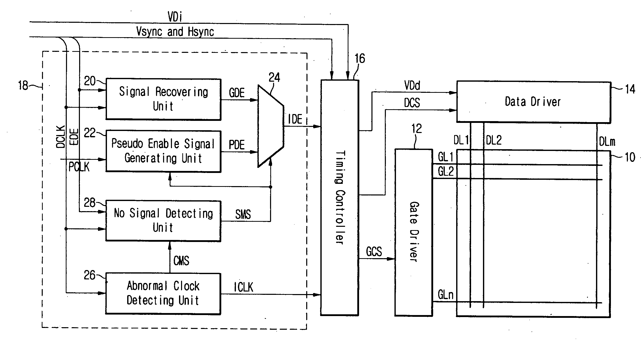
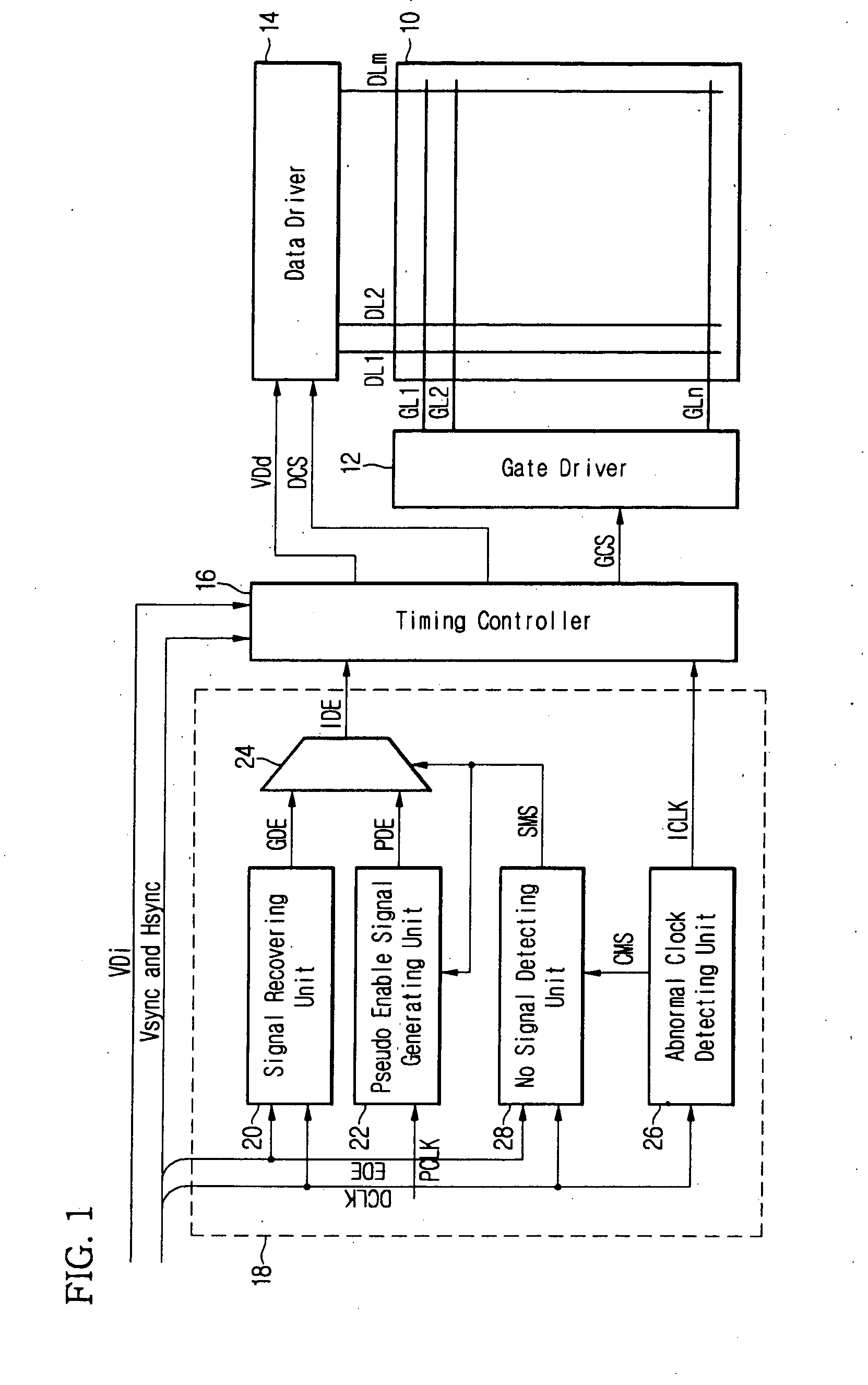
[0029]FIG. 1 is a block diagram of an LCD device including a picture mode controller according to an exemplary embodiment of the present invention. Though the LCD device illustrated in FIG. 1 is described as an embodiment of the present invention, it would be obvious to a person of ordinary skill in the art that various modifications can be made without departing from the spirit and scope of the present invention. For example, the present invention can be applied to a plasma display device and an electric field light-emitting display device.

[0030]As shown in FIG. 1, the LCD device includes a gate driver 12 connected to a plurality of gate lines GL1-GLn on an liquid crystal LC panel 10, and a data driver 14 connected to a plurality of data lines DL1-DLm on the LC panel 10. The plurality of gate lines GL1-GLn and data lines DL...


PUM


Abstract

The picture mode controller for flat panel and flat panel display device including the same includes an input unit to input a first timing signal indicating transmission sections for pixel data, and a second timing signal indicating a transmission time of each pixel data, a pseudo timing signal generating unit to generate a first pseudo timing signal to be used as the first timing signal, a first selecting unit to selectively output the first timing signal and the first pseudo timing signal to allow one of a video picture mode and a black picture mode to be designated, and a selection control unit to control a selecting operation of the first selecting unit based on whether the first timing signal is input from the input unit and whether a period of the second timing signal changes.

Description

[0001]This application claims the benefit of the Korean Patent Application No. 10-2006-0119911 filed on Nov. 30, 2006, which is hereby incorporated by reference.BACKGROUND OF THE INVENTION[0002]1. Field of the Invention[0003]The present invention relates to a flat panel display device for displaying an image on a flat panel, and more particularly, to a picture mode controller for selecting one of a video image and a black image on a flat panel, a flat panel display device including the same, and a driving method thereof.[0004]2. Discussion of the Related Art[0005]Flat panel displays such as general liquid crystal panels, plasma display panels, and electro luminescence display panels include pixels formed in respective unit regions defined by scan lines (gate lines) and data lines (source lines). A flat panel display can provide a large screen while having a remarkably thin thickness compared to a cathode ray tube (CRT). Furthermore, flat panel displays make it possible to manufactur...

Claims


Application Information

Patent Timeline
Patent Type & Authority Applications(United States)
IPC IPC(8): G09G5/10
CPCG09G3/2096G09G3/3611G09G2340/0407G09G2310/061G09G5/008G09G3/36G09G3/20G02F1/133
Inventor KIM, JIN SUNGKIM, MIN KI
Owner LG DISPLAY CO LTD
Learn More