Optical system and optical apparatus including optical system

Inactive Publication Date: 2008-06-05
CANON KK
View PDF15 Cites 21 Cited by
  • Summary
  • Abstract
  • Description
  • Claims
  • Application Information

AI Technical Summary

Benefits of technology

[0015]The present invention is directed to an optical system that can sufficiently correct a variety of aberrations including chromatic aberration, tha

Problems solved by technology

In general, as the size of an optical system decreases, the aberrations and, in particular, the axial chromatic aberration and the chromatic aberration of magnification of the optical system significantly increase.
Thus, the optical performance of the optical system decreases.
In telephoto optical systems having a short total lens length, as the focal length increases, chromatic aberration increases.
Thus, a negative distortion aberration (barrel distortion aberration) and chromatic aberration of magnification tend to occur.
However, as the lens length decreases, occurrence of chromatic aberration of magnification significantly increases.
It is difficult to sufficiently correct such a chromatic aberration.
However, if the refractive power of the lens surface is significantly changed, a variety of aberrations, such as spherical aberration, coma aberration, and astigmatism aberration, occur.
Accordingly, it is difficult to correct chromatic aberration and

Method used


Image

  • Optical system and optical apparatus including optical system
  • Optical system and optical apparatus including optical system
  • Optical system and optical apparatus including optical system

Examples


Example

First Exemplary Embodiment

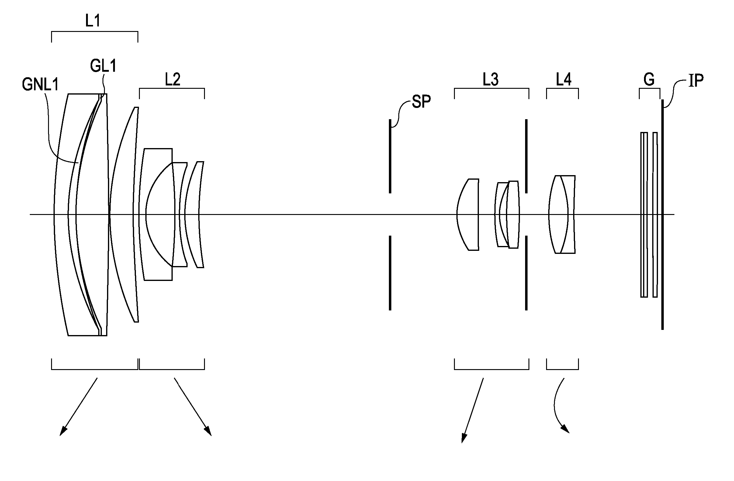
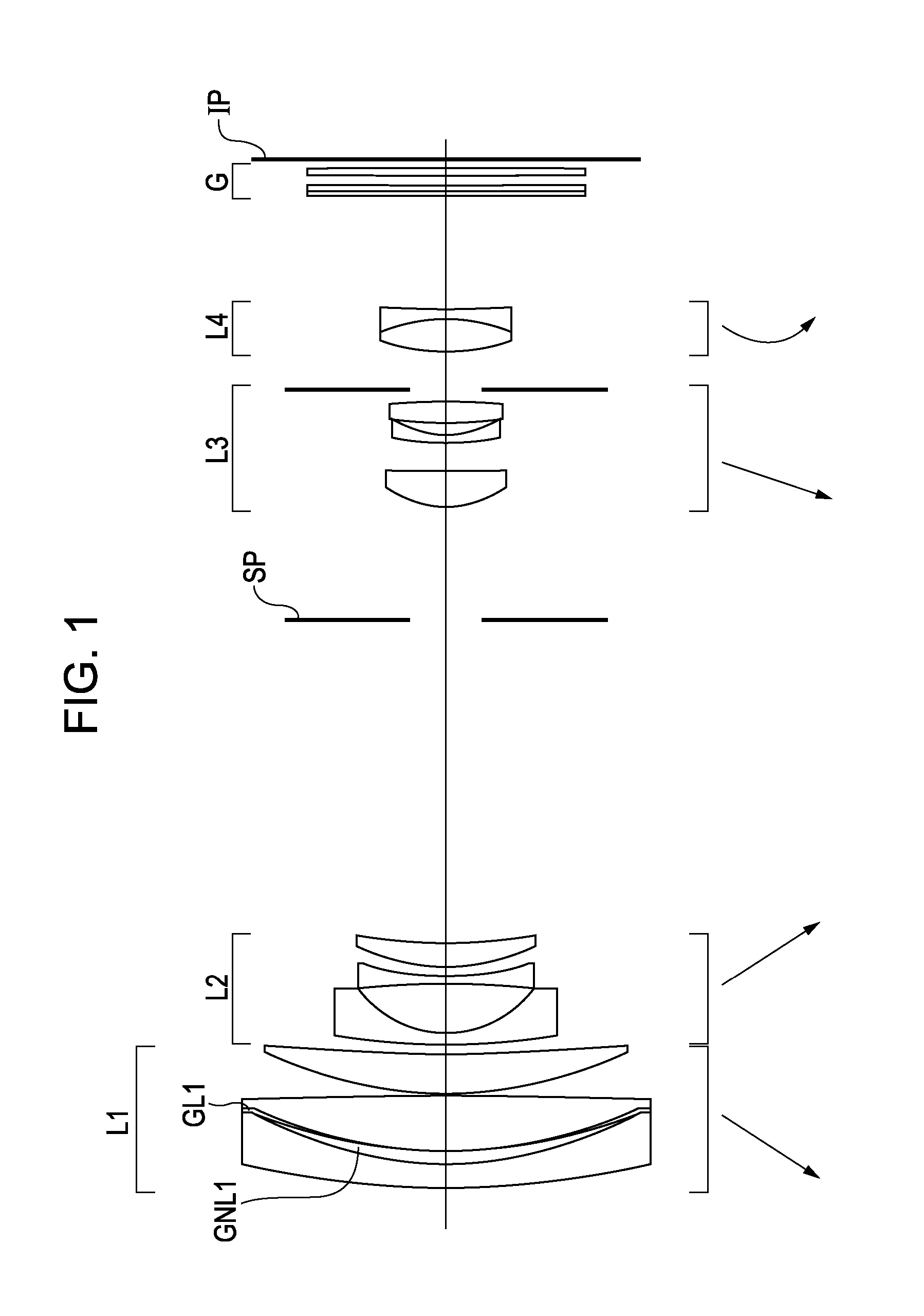
[0062]According to a first exemplary embodiment, an optical system includes a refractive optical element (hereinafter also referred to as an “optical element”) obtained by providing a refractive function to a solid material that satisfies the following conditions.

[0063]As used herein, the term “solid material” of the refractive optical element refers to a material that is solid in a use environment of the optical system. Accordingly, the material may be in any state before the optical system is in use (e.g., during a fabrication period). For example, even when the material is liquid during a fabrication period, the material is referred to as a “solid material” if the liquid material is cured into a solid material.

[0064]The features of an optical system OL according to the present embodiment is as follows.

[0065]A paraxial marginal ray is a paraxial ray that, when the focal length of the entire optical system is normalized to “1”, travels parallel to the ligh...

Example

[0165]According to the seventh exemplary embodiment, as shown in FIG. 13, the optical system is a wide-angle lens having a focal length of 24.5 mm. The optical system includes a first lens group L1 having a negative refractive power, a second lens group L2 having a negative refractive power, and a third lens group L3 having a positive refractive power. The first lens group L1 is moved along the light axis for a focusing purpose.

[0166]According to the present exemplary embodiment, the lens (layer) GNL1 composed of the UV-curable resin 1 is employed as part of the optical system. In addition, the lens (layer) GL1 composed of a mixture of the UV-curable resin 2 and 5% by volume ITO fine particles dispersed therein is employed.

[0167]According to the seventh exemplary embodiment, the optical system includes the lens (layer) GNL1 composed of a UV-curable resin and having a positive refractive power and the lens (layer) GL1 composed of a mixture including ITO fine particles and having a ne...

Example

[0270]According to the eighth embodiment, the first lens group L1 includes the lens (layer) GNL1 and the lens (layer) GL1 on the object side where, when the paraxial marginal ray passes through the first lens group L1, the height of the paraxial marginal ray from the light axis is relatively large. In addition, the lens GNL1 and the lens GL1 are in tight contact with each other. The contact surface is aspherical. The lens GNL1 and the lens GL1 are cemented between the other lenses. In this way, axial chromatic aberration and chromatic aberration of magnification are sufficiently corrected. Thus, a compact telephoto lens having a telephoto ratio of 0.764 can be achieved.

[0271]According to a ninth exemplary embodiment, as shown in FIG. 17, the optical system is a telephoto lens having a focal length of 300 mm. The optical system includes a first lens group L1 having a positive refractive power, a second lens group L2 having a negative refractive power, and a third lens group L3 having...


PUM


Abstract

An optical system includes a first optical element and a second optical element on at least one of an enlargement side and a reduction side relative to a point P at which a light axis and a paraxial chief ray intersect. Each of the first optical element and second optical element is composed of a solid material having a refractive light incident surface and a refractive light emergent surface. The optical system satisfies the following conditional expressions: ΔθgF1>0.0272, ΔθgF2<−0.0278, and f1×f2<0 where ΔθgF1 and ΔθgF2 denote anomalous partial dispersion values of the first and second optical elements for the g-line and F-line, respectively, and f1 and f2 denote focal lengths of the first and second optical elements, respectively, when the light incident surfaces and the light emergent surfaces of the first and second optical elements are in contact with air.

Description

BACKGROUND OF THE INVENTION[0001]1. Field of the Invention[0002]The present invention relates to an optical system and, in particular, an optical system suitable for optical apparatuses, such as silver-halide film cameras, digital still cameras, video cameras, digital video cameras, telescopes, binoculars, projectors, and copying machines.[0003]2. Description of the Related Art[0004]Optical systems used for optical apparatuses, such as digital cameras and video cameras, need to have a short total lens length (optical length: the length between the first lens surface on the object side and the image plane) and the short length of the optical systems. In general, as the size of an optical system decreases, the aberrations and, in particular, the axial chromatic aberration and the chromatic aberration of magnification of the optical system significantly increase. Thus, the optical performance of the optical system decreases.[0005]In telephoto optical systems having a short total lens l...

Claims


Application Information

Patent Timeline
IPC IPC(8): G02B9/34G02B9/14G02B9/12
CPCG02B27/0062G02B15/173G02B15/144113
Inventor ISHIBASHI, TOMOHIKO
Owner CANON KK
Why Eureka
Try Eureka