Image decoding technique for suppressing tile boundary distortion

a decoding technique and tile technology, applied in the field of image processing techniques, can solve the problems of discontinuous tile boundary discontinuity (or distortion), not desirable to overlap adjacent tile boundary, and difficult to achieve the effect of reducing memory requirements, increasing processing speed, and reducing boundary artifacts

Inactive Publication Date: 2008-06-05
RICOH KK
View PDF17 Cites 37 Cited by
  • Summary
  • Abstract
  • Description
  • Claims
  • Application Information

AI Technical Summary

Benefits of technology

[0013]Further, in order to solve such a problem, there has been proposed a technique that makes tile boundaries less conspicuous by performing low-pass filtering evenly only on the periphery of the tile boundaries.
[0035]Additionally, in the above-described method, step (a) may be prevented from performing the smoothing of tile boundary distortion when the ratio of the decoding quantity to the entire quantity of the compressed code exceeds a predetermined threshold.

Problems solved by technology

1290-1295, 20-23 Jun., 2000, Perth, Australia, there is a problem in that performing compression and decompression at a high compression rate results in a decompressed image with discontinuous tile boundaries.
That is, such tile boundary discontinuity (or distortion) is likely to be conspicuous in the decompressed image.
Therefore, it is not desirable to overlap adjacent tile boundaries in terms of compliance with the JPEG2000 provisions.
However, if the edge degree is strong in the tile boundaries, the low-pass filtering blurs the edges around the tile boundaries, so that the degradation of image quality appears as stripes.

Method used


Image

  • Image decoding technique for suppressing tile boundary distortion
  • Image decoding technique for suppressing tile boundary distortion
  • Image decoding technique for suppressing tile boundary distortion

Examples


first embodiment

[0127]Next, a description will be given of a first embodiment of the present invention.

[0128]FIG. 7 is a diagram showing a system including an image processing apparatus 1 according to the first embodiment of the present invention. FIG. 8 is a functional block diagram of the image processing apparatus 1. As shown in FIG. 7, the image processing apparatus 1 is a personal computer, for instance, and is connectable via a network 5, which may be the Internet, to a server computer S storing and retaining a variety of image data.

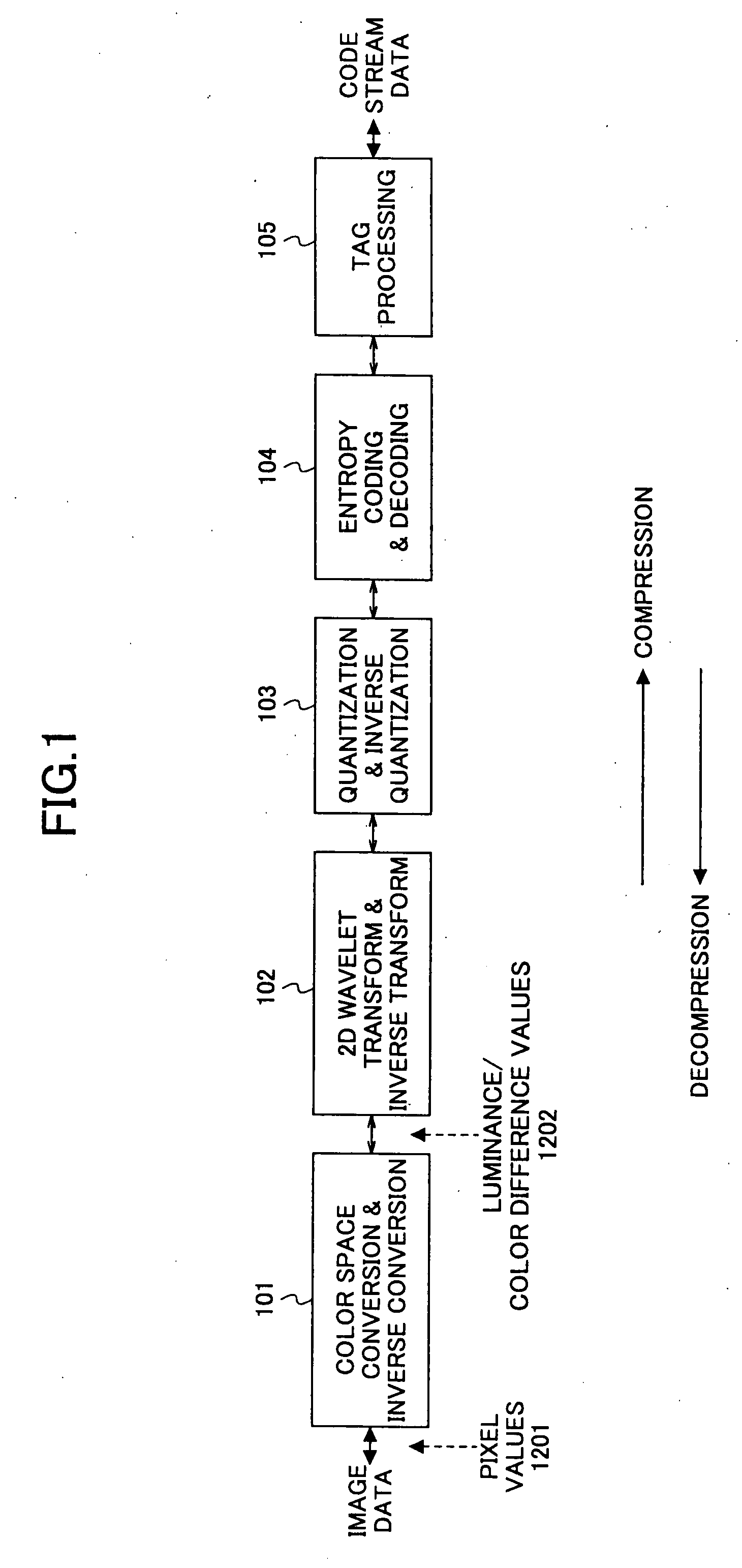
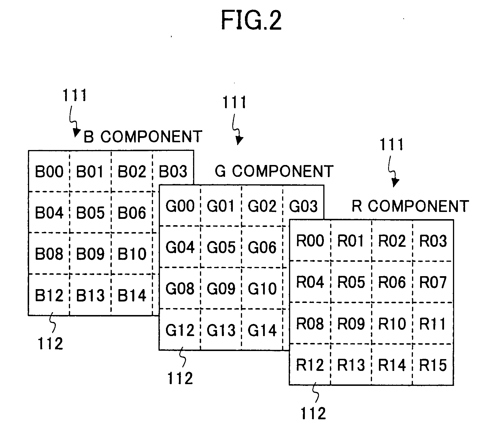
[0129]In this embodiment, the image data stored in the server computer S are compressed codes generated in accordance with the JPEG2000 algorithm. More specifically, a two-dimensionally divided image as shown in FIG. 9 is subjected to compression coding and arranged one-dimensionally, so that a compressed code as shown in FIG. 10 is generated. In FIG. 10, SOC is a marker segment indicating the start of a code stream. MH refers to a main header storing values commo...

second embodiment

[0156]Next, a description will be given of a second embodiment of the present invention. In this embodiment, the same elements as those described in the first embodiment are referred to by the same numerals, and a description thereof will be omitted. The second embodiment differs from the first embodiment in the function of the image decompressor 2. Schematically, low-pass filtering is performed not on the peripheral pixels of every tile boundary, but on the peripheral pixels of only a specified tile boundary.

[0157]FIG. 19 is a functional block diagram of the image decompressor 2 according to the second embodiment. As shown in FIG. 19, by the CPU 6 operating based on the computer software (image processing program), the image decompressor 2 realizes the functions of the decoding quantity specifying part 20, the tag processing part 21, the entropy decoding part 22, the inverse quantization part 23, the 2D wavelet inverse transform part 24, the color space inverse conversion part 25, ...

third embodiment

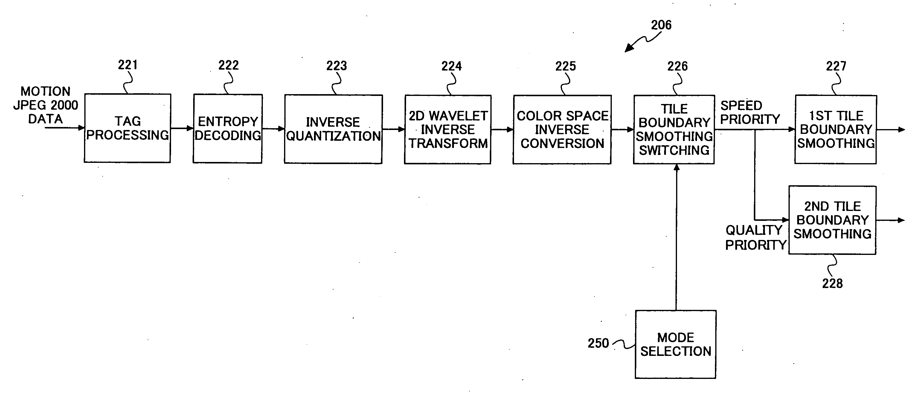
[0166]A description will be given of a third embodiment of the present invention. This embodiment relates to a moving image compression and decompression technique represented by “Motion JPEG2000.” In the “Motion JPEG2000 algorithm,” the “JPEG2000 algorithm,” which is applied to a still image, or a single frame, is extended to be applied to a plurality of frames. That is, as shown in FIG. 22, “Motion JPEG2000” successively displays single-frame JPEG2000 images at a predetermined frame rate as a moving image.

[0167]FIG. 23 is a diagram showing a monitor camera system 201 according to the third embodiment. FIG. 24 is a functional block diagram of the monitor camera system 201. As shown in FIG. 23, the monitor camera system 1, to which a moving image display system according to the present invention is applied, includes a monitor camera 201a functioning as an image recorder and a personal computer (PC) 201b functioning as an image processor. The monitor camera 201a and the PC 201b are c...


PUM


Abstract

An image decoding device for decoding a hierarchically encoded compressed code obtained by dividing an image into a plurality of tiles and performing discrete wavelet transform on the pixel values of the image tile by tile includes a tile boundary smoothing part that performs smoothing of tile boundary distortion on the image after the decoding by application of a low-pass filter. The tile boundary smoothing part controls the degree of smoothing of the low-pass filter according to the ratio of the decoding quantity to the entire quantity of the compressed code. The decoding quantity is the portion of the compressed code which portion is to be decoded.

Description

CROSS REFERENCE TO RELATED APPLICATIONS[0001]This application is a Continuation of and is based upon and claims the benefit of priority under 35 U.S.C. §120 for U.S. Ser. No. 10 / 600,333, filed Jun. 23, 2003, and claims the benefit of priority under 35 U.S.C. § 119 from Japanese Patent Application No. 2002-208107, filed Jul. 17, 2002, Japanese Patent Application No. 2002-208156, filed Jul. 17, 2002, and Japanese Patent Application No. 2002-267692, filed Sep. 13, 2002, the entire contents of each which are incorporated herein by reference.BACKGROUND OF THE INVENTION[0002]1. Field of the Invention[0003]The present invention generally relates to image processing techniques for controlling the distortion of an inter-unit boundary in the case of decompressing, unit by unit, a compressed image divided into predetermined units, and more particularly to an image decoding device, an image processing apparatus, and an image processing method suitable for suppressing a tile boundary distortion ...

Claims


Application Information

Patent Timeline
Patent Type & Authority Applications(United States)
IPC IPC(8): G06K9/36G06T5/20G06T9/00H04N7/26H04N7/30
CPCG06T5/20H04N19/10H04N19/172H04N19/63H04N19/117H04N19/86H04N19/157H04N19/17H04N19/44H04N19/645H04N19/152
Inventor SUINO, TOORUSAKUYAMA, HIROYUKI
Owner RICOH KK
Why Eureka
Try Eureka