Pneumatic Uneven Flow Factoring For Particulate Matter Distribution System

a technology of pneumatic and uneven flow factoring, applied in the direction of bulk conveyors, conveyors, transportation and packaging, etc., can solve the problems of reducing the life cycle of tube materials, imbalances that can produce significant variations, and adverse environmental consequences, so as to achieve the effect of reducing the effectiveness or efficiency of the process and not further compromising the effect of the process

Inactive Publication Date: 2008-06-05
PEET WILLIAM JEFFREY
View PDF27 Cites 1 Cited by
  • Summary
  • Abstract
  • Description
  • Claims
  • Application Information

AI Technical Summary

Benefits of technology

[0010]An advantage of the present invention is that the flow of particulate matter (i.e., solids flow) within a number of conduits is substantially balanced.
[0011]A further advantage of the present invention is that the substantially balanced flow of particulate matter (i.e., solids flow) within the conduits is achieved without further compromising the effectiveness or efficiency of the process in which they are installed.
[0012]A still further advantage of the present invention is that flow control of particulate matter (i.e., solids flow) within the conduits is achievable under all load conditions in a simple closed loop control system.
[0013]A yet further advantage of the present invention is that a single pressurized fluid source or separate pressurized fluid source(s) can be employed to achieve flow control of particulate matter (i.e., solids flow) within the conduits.
[0014]A still yet further advantage of the present invention is that different pressurized fluids that are maintained at different temperatures can be employed to achieve flow control of particulate matter (i.e., solids flow) within the conduits.
[0015]Other features and advantages of the present invention will be apparent from the following more detailed description of the preferred embodiment, taken in conjunction with the accompanying drawings which illustrate, by way of example, the principles of the invention.

Problems solved by technology

A substantially balanced flow of coal particles is highly desirable, as an imbalanced flow of coal particle fuel to the burners can result in significant emissions of nitrogen oxides (NOx) and carbon monoxide (CO), having adverse environmental consequences.
In addition, the imbalance can produce a significant variation in the absorptions throughout the boiler surfaces located after the furnace.
This imbalance causes additional steam temperature variations among the superheater and reheater tubes which can reduce the life cycle of the tube material and produce lower overall efficiencies.
However, continuously balanced particulate flow is extremely difficult to achieve, and conventional techniques employed not only fail to provide balanced particulate flow, but also decrease the efficiency of the conveyance system.
Applying either of the above techniques cannot achieve a balanced system, i.e., equal distribution of the solids mass flow within each conduit, in a continuous operating regime.
Thus, an allowable margin is generally adopted for the acceptance of the final arrangement and this typically results in an imbalanced system, i.e., unequal and varying distribution of the solids mass flow within each conduit.
An imbalanced system, even at + / −5% of the mean pneumatic velocity (or mass flow), can have a significant negative impact on the operation of a process that relies on equal distribution of the solids mass flow within each conduit for optimum performance.
In summary, existing techniques for balancing the flow of particulate matter (solids flow) within a number of conduits are inadequate and compromise the effectiveness or efficiency of the process in which they are installed.

Method used


Image

  • Pneumatic Uneven Flow Factoring For Particulate Matter Distribution System
  • Pneumatic Uneven Flow Factoring For Particulate Matter Distribution System
  • Pneumatic Uneven Flow Factoring For Particulate Matter Distribution System

Examples


Embodiment Construction

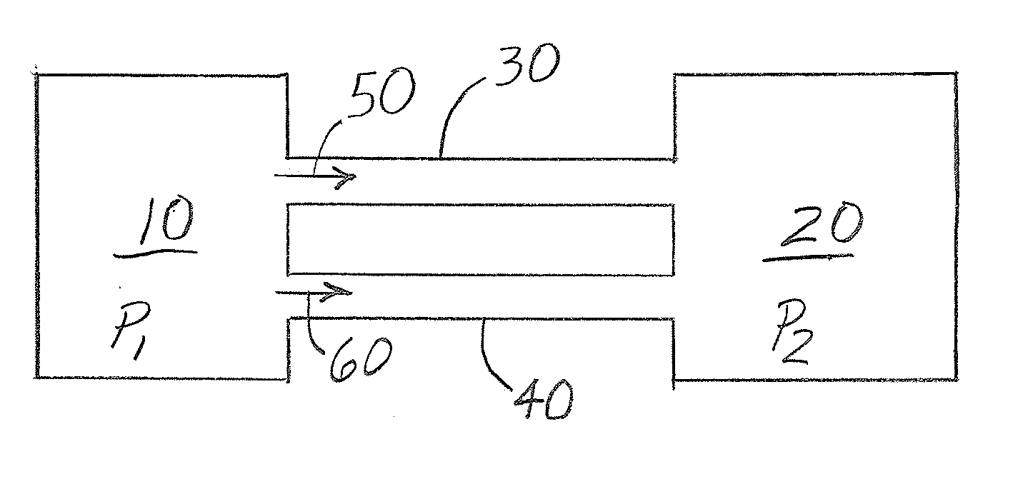
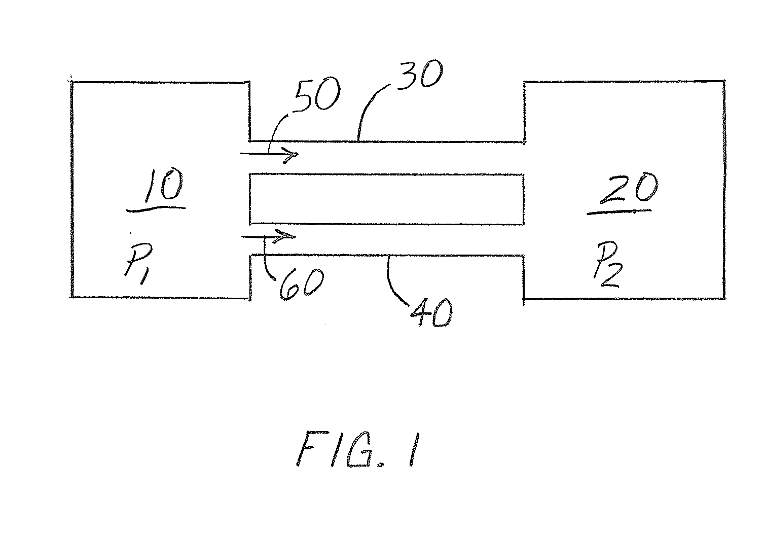
[0021]The present invention applies to a system and method for substantially balancing or equalizing the mass flow of fine solids or finely rendered particulate matter conveyed along two or more conduits by pressurized fluid. Each conduit extends from a common first position to a second position, the conduits defining separate pathways each having substantially equal pressure reductions between the first and second positions. It is to be understood that the size of particulate matter can vary, so long as the particulate matter is entrained(able) in the flow of the pressurized fluid, or at least is controllably movable within the conduits by the pressurized fluid. In one embodiment, the pressurized fluid for use in the system and method of the present invention is a gas, although it is possible for a proportion of the pressurized fluid to be a vapor.

[0022]It is to be understood that the terms solids, including the subscripted “s” for certain terms to be discussed below, and particula...


PUM


Abstract

A system is provided for distributing particulate matter. The system includes at least two conduits, each conduit extending from a common first position adjacent a source of particulate matter to a second position. The pressure differential between the first and second positions is substantially the same for each conduit. A pressurized fluid conveys particulate matter through the at least two conduits. A device measures mass flow of particulate matter in each of the at least two conduits. A controller is in communication with the device that provides additional pressurized fluid to each conduit having a solids ratio greater than the desired solids ratio of the at least two conduits in response to a measured mass flow rate to balance (or to preferentially bias) mass flow of particulate matter through each of the at least two conduits.

Description

FIELD OF THE INVENTION[0001]The present invention relates generally to distribution systems and, more particularly, to a particulate matter distribution system.BACKGROUND OF THE INVENTION[0002]Particulate matter distribution systems are generally associated with conveying a mass flow of finely rendered solid particles from a common source to multiple destinations, preferably providing equal amounts of the particulate matter to each destination. One method of conveying the particulate matter includes the provision of pressurized air. In one application, a pneumatic distribution system includes a number of pathways or conduits for continuously conveying finely pulverized coal to respective burners of a furnace, i.e., a coal fired furnace. A substantially balanced flow of coal particles is highly desirable, as an imbalanced flow of coal particle fuel to the burners can result in significant emissions of nitrogen oxides (NOx) and carbon monoxide (CO), having adverse environmental conseq...

Claims


Application Information

Patent Timeline
Patent Type & Authority Applications(United States)
IPC IPC(8): B65G51/16B65G53/04
CPCB65G53/66
Inventor PEET, WILLIAM JEFFREY
Owner PEET WILLIAM JEFFREY
Why Eureka
Try Eureka