Transponder embedded in a flexible multilayer support

a multi-layer support and transponder technology, applied in the field of contactless transponders embedded in flexible multi-layer supports, can solve the problems of insufficient surface and appearance quality to meet market requirements, thin or more flexible transponders, and at the cost of weakening their stress resistance and mechanical solidity, almost “evanescent” foils have been apparently considered as not reliable substrates for transponders, etc., to achieve easy penetration, less time and energy consumption, and easy lamination

Active Publication Date: 2008-06-05
HID GLOBAL GMBH
View PDF15 Cites 24 Cited by
  • Summary
  • Abstract
  • Description
  • Claims
  • Application Information

AI Technical Summary

Benefits of technology

[0030]The invention further relates to the manufacture of the transponder. Preferably, the multi-layer laminate support is assembled as a stack and then laminated together with the electronic unit inside the stack. This results in a planar laminate structure where the non-woven foils are at least partially embe

Problems solved by technology

However, such an inlay presents a surface and an appearance quality that are not sufficient to meet market requirements.
By using smoother plastic such as polyurethane (PU) or polyethylene terephthalate glycol (PET-G) and other equivalent materials,

Method used


Image

  • Transponder embedded in a flexible multilayer support
  • Transponder embedded in a flexible multilayer support
  • Transponder embedded in a flexible multilayer support

Examples


first embodiment

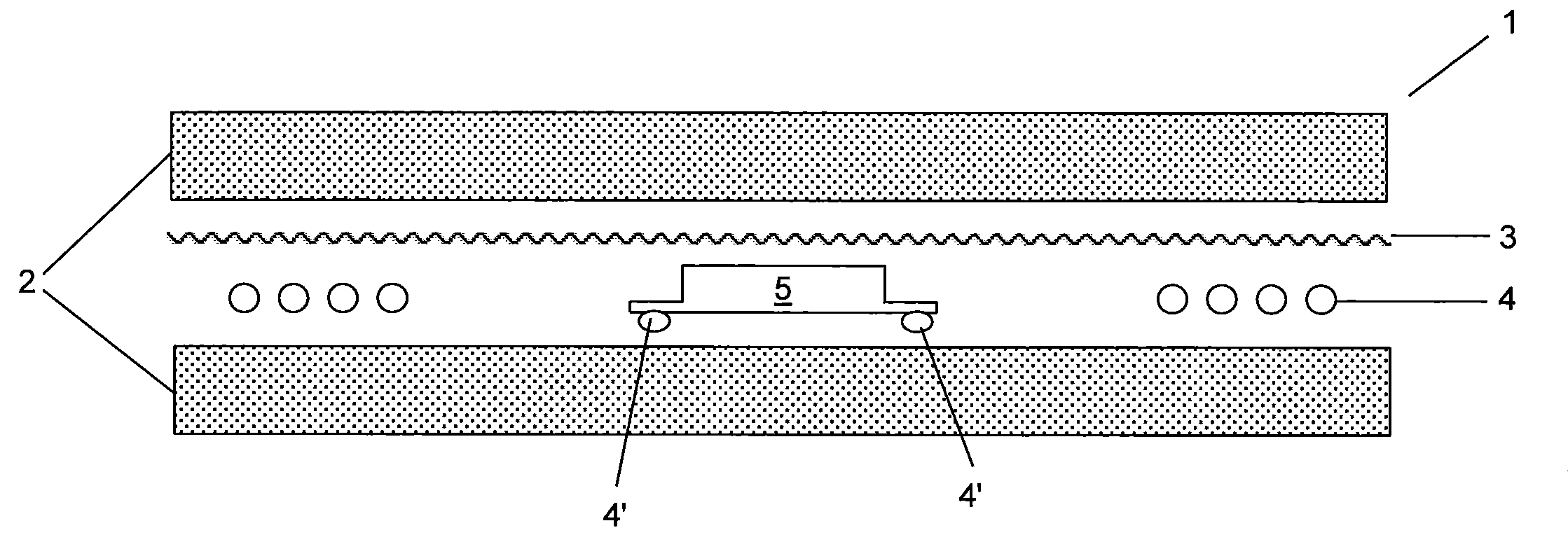
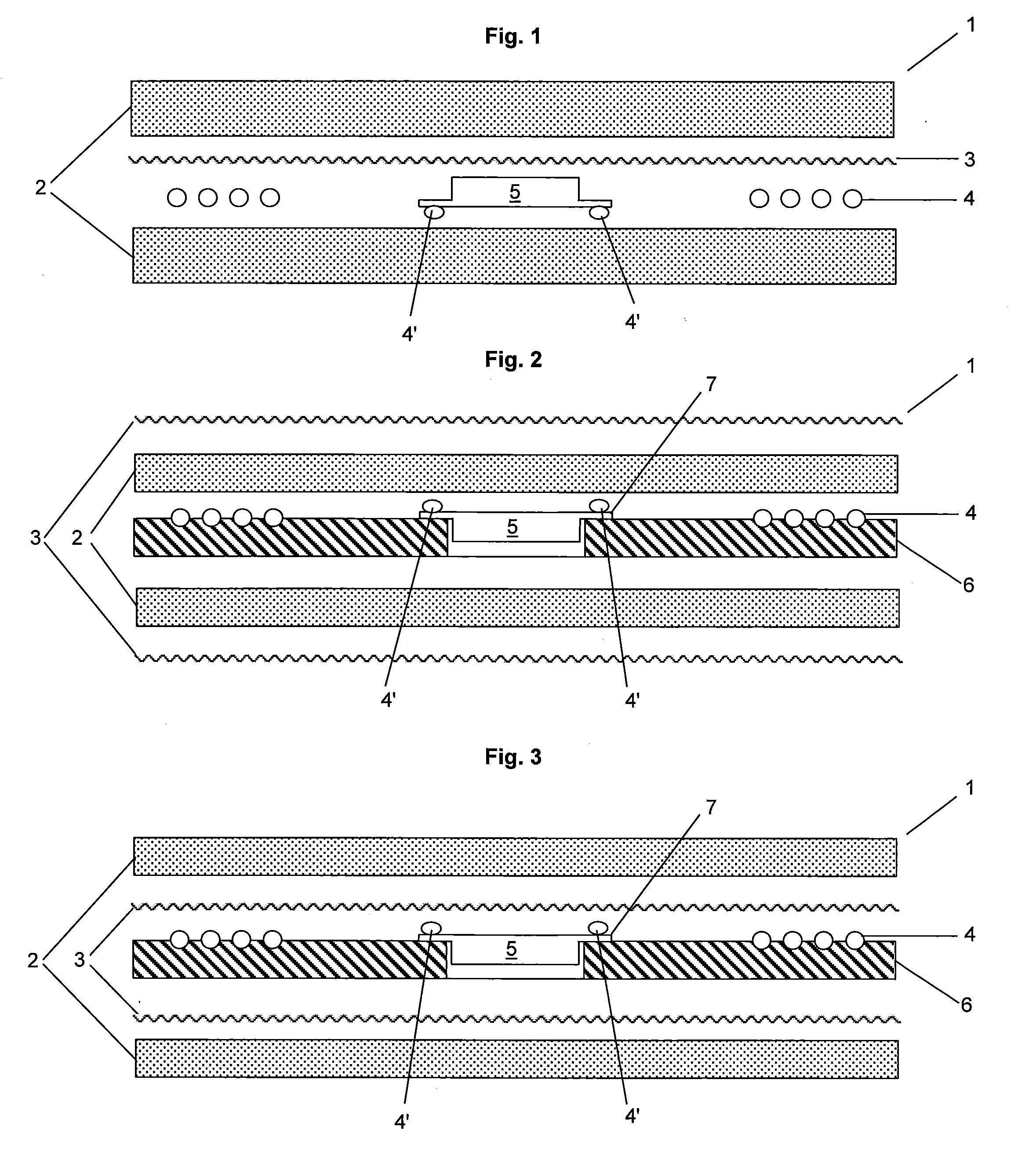
[0039]FIG. 1 shows the multi-layer laminate support 1 of the invention which comprises a chip module 5 to which an antenna coil 4 is connected by contact ends 4′, said chip module and antenna being placed between two thermoplastic layers 2. According to the invention, there is, in addition to the two thermoplastic layers 2, a further layer 3 which is a non-woven foil. This foil 3 is shown placed on top of the antenna 4 and module 5, but it can of course also be placed underneath said antenna 4 and module 5.

[0040]The non-woven substrate 3 is very thin, in particular in comparison to the antenna coil. It is made of non-woven long fibers put together in the form of a sheet and bonded, either mechanically, by thermal bonding, by chemical bonding (binder, adhesive), by hydro-entanglement, by needle felt, etc. In the present invention one envisages the use of a very thin and very porous type of non-woven sheet, presenting long fibers and small quantities of bonding material (if used). The...

second embodiment

[0048]In another variant, it is also possible to combine the first and second embodiment illustrated in FIGS. 1 and 2 and to use a first non-woven foil 3 placed between the two thermoplastic layers (as in FIG. 1) and a second non-woven foil placed over one (or two) thermoplastic layer(s).

[0049]FIG. 3 illustrates a further embodiment of the present invention, where two non-woven foils 3 are placed between the two thermoplastic layers 2, one foil on each side of the module 5 and antenna 4. In this embodiment, as in the one illustrated in FIG. 2, the antenna 4 and the chip 5 are placed on a core layer 6.

[0050]Any combination of the illustrative embodiments of FIGS. 1 to 3 can of course be envisaged with the addition of a foil of non-woven material in any a designated position.

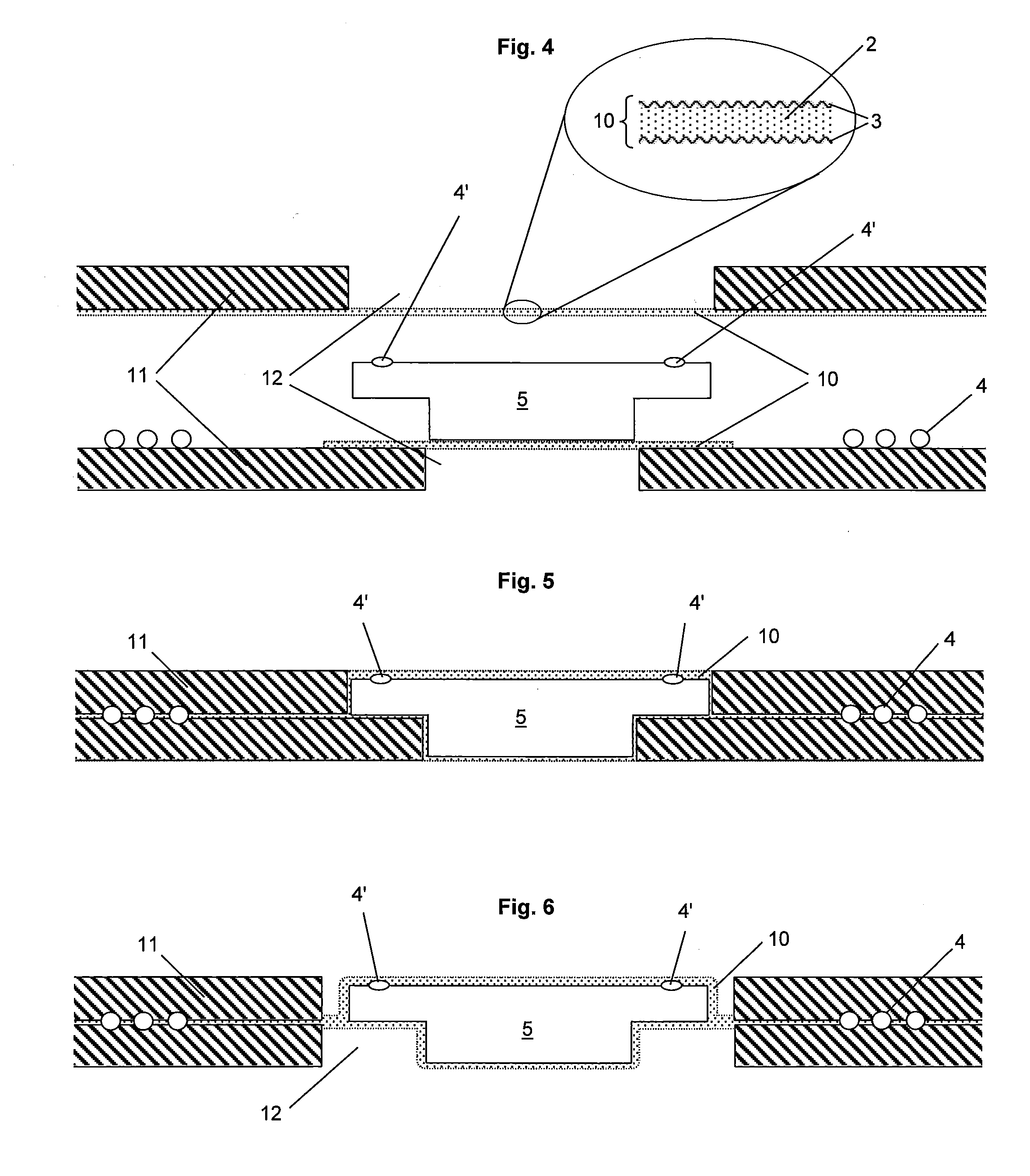
[0051]FIG. 4 shows another embodiment of the transponder according to the present invention. In this embodiment, the non-woven foil 3 and the soft thermoplastic layer 2 are combined to form an embedding patch 10. ...


PUM

PropertyMeasurementUnit
Thicknessaaaaaaaaaa
Diameteraaaaaaaaaa
Flexibilityaaaaaaaaaa

Abstract

The transponder with an electronic unit comprising an antenna coil (4) connected to a chip module (5) embedded in a multi-layer laminate support (1) comprises at least one flexible thermoplastic layer (2) disposed on both sides of the electronic unit wherein the multi-layer laminate support further comprises a non-woven foil (3) with a grammage of less than 25 g/m2.

Description

FIELD OF THE INVENTION[0001]The present invention relates to a contactless transponder embedded in a flexible multi-layer support, and more particularly, to the way such a transponder is mounted in a flexible multi-layer laminate support. More specifically, the invention concerns, the substrate structure to be used to obtain extremely flexible transponders, while keeping the mechanical stability and the stress resistance of classical rigid laminated structures. Inlays for contactless smart cards or for any other laminated structures in which the transponder has to be embedded are one of the particular embodiments of the invention.STATE OF THE ART[0002]Contactless information carriers such as contactless IC cards have been an expanding technology for years and are now developing into a mature market. One of the most important technical tasks one is faced with is how to simplify the production steps and reduce the unit costs.[0003]Contactless ID cards have been produced for many years...

Claims


Application Information

Patent Timeline
IPC IPC(8): B32B3/10B32B27/14
CPCB32B27/12B42D2033/46G06K19/07722G06K19/07728G06K19/07749B42D15/10B42D25/00Y10T428/27Y10T428/2481Y10T428/26B42D15/0013B42D25/29Y10T442/2746Y10T442/674Y10T442/20Y10T442/2738Y10T442/2754B42D25/45
Inventor MICHALK, MANFRED
Owner HID GLOBAL GMBH
Why Eureka
Try Eureka