Battery Pack and Method for Welding Cells

Active Publication Date: 2008-06-05
HITACHI VEHICLE ENERGY
View PDF2 Cites 22 Cited by
  • Summary
  • Abstract
  • Description
  • Claims
  • Application Information

AI Technical Summary

Problems solved by technology

If the connection resistance (electric resistance) between them is large, conduction loss due to voltage drop increases an

Method used


Image

  • Battery Pack and Method for Welding Cells
  • Battery Pack and Method for Welding Cells
  • Battery Pack and Method for Welding Cells

Examples


Embodiment Construction

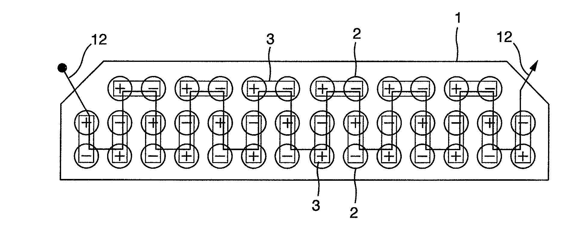
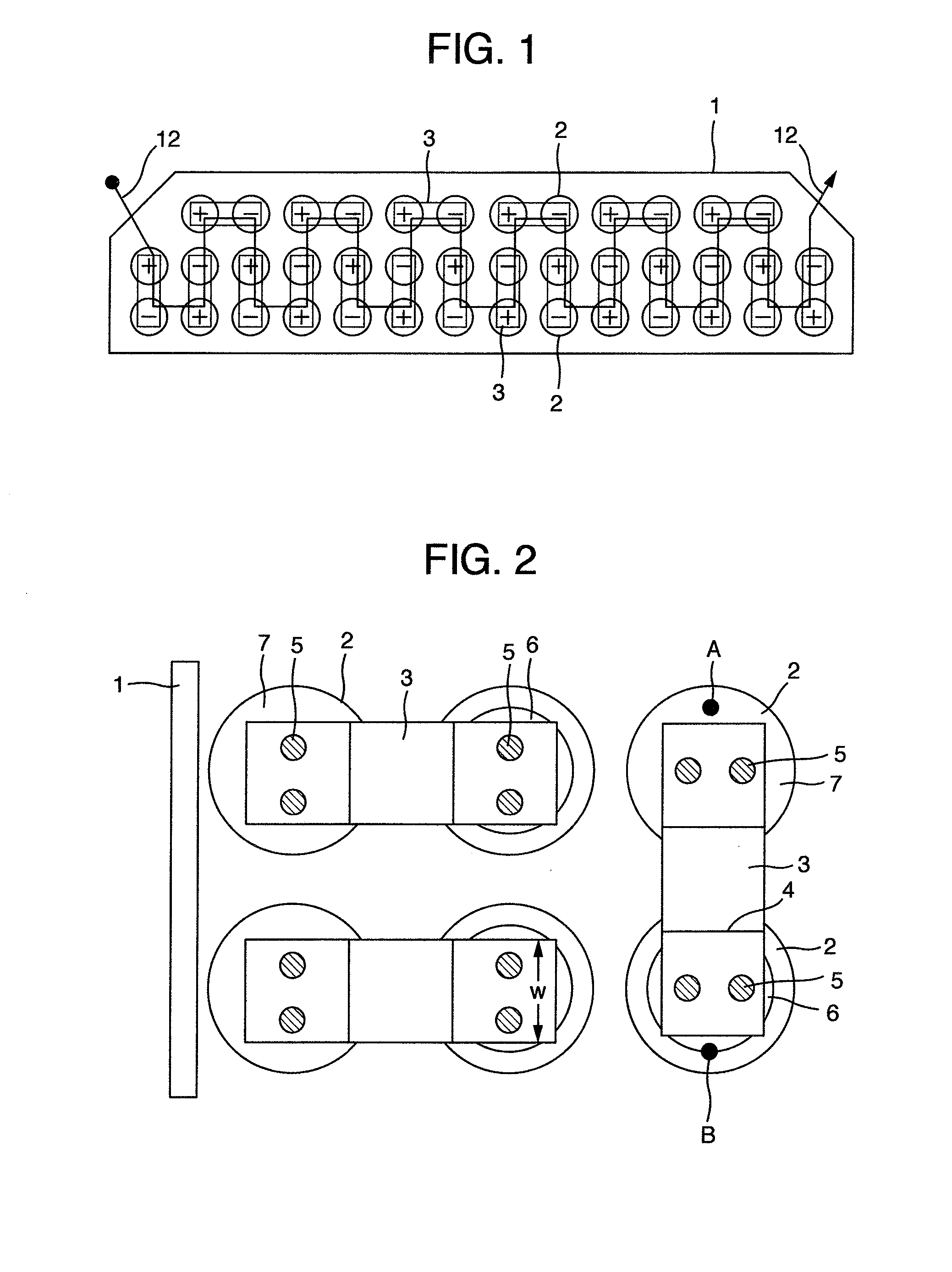
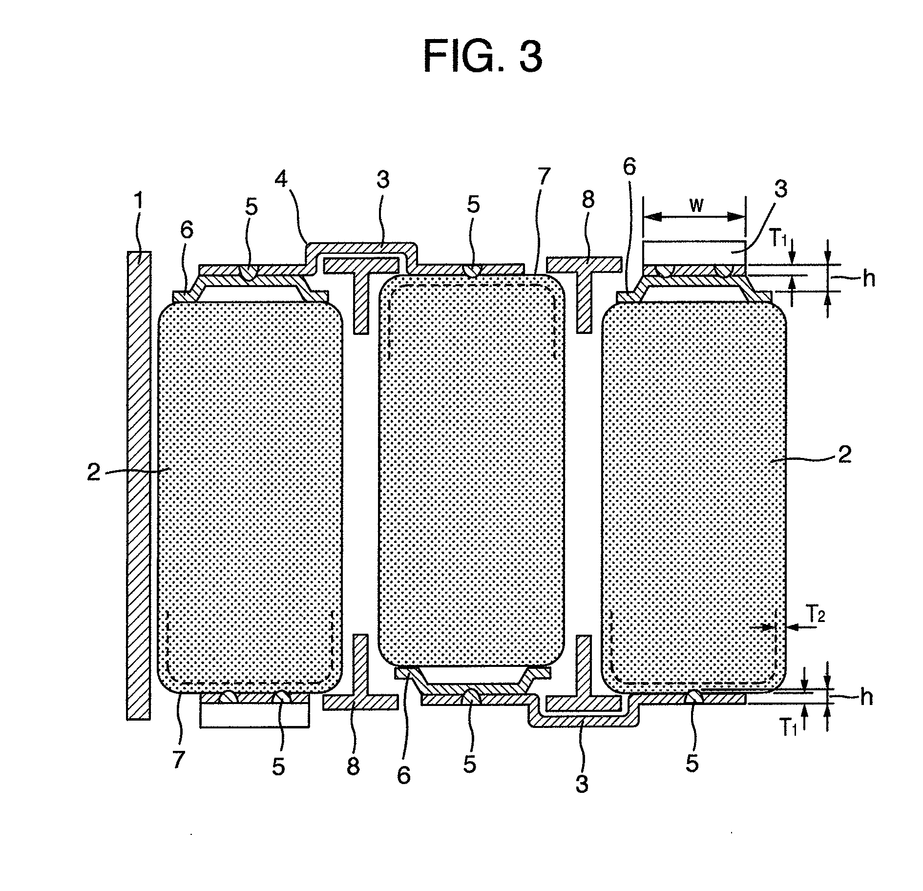
[0030]A battery pack and a welding method therefor according to preferred embodiments will be described with reference to the accompanying drawings. FIG. 1 is a diagram illustrating an arrangement of battery cells, connections between positive and negative electrodes of the battery cells, and current paths of a battery pack according to one exemplary embodiment of the present invention. FIG. 2 is a top view showing one exemplary embodiment of the connections between positive and negative electrodes of the battery cells shown in FIG. 1. FIG. 3 is a cross-sectional view showing the connections between the positive and negative electrodes of the battery cells shown in FIG. 2. FIG. 4 is a flowchart and a cross-sectional view illustrating the steps of disposing a connecting metallic plate and performing arc spot welding that relate to a battery pack and welding method therefor according to the present invention.

[0031]As shown in FIG. 1, a set of 40 battery cells 2 is arranged in multiple...


PUM

PropertyMeasurementUnit
Thicknessaaaaaaaaaa
Thicknessaaaaaaaaaa
Lengthaaaaaaaaaa

Abstract

In a battery pack in which multiple battery cells are arranged in one or multiple rows in an electrically insulating case and an electrode of each battery cell is coupled to an electrode of another battery cell through a connecting metallic plate, the connecting metallic plate made of copper is disposed on a positive electrode of each battery cell and on a negative electrode of another battery cell to form a lap joint, and a weld is formed in each of one predetermined position on the connecting metallic plate 3 above the positive electrode and another predetermined position on the connecting metallic plate above the negative electrode by applying arc spot welding. The depth h of weld penetration in the weld is greater than the thickness T1 of the connecting metallic plate and smaller than the thickness T1 plus the thickness T2 of the positive electrode or the negative electrode, that is, T1<h≦(T1+T2×4/5).

Description

BACKGROUND OF THE INVENTION[0001]The present invention relates to a battery pack in which a positive electrode of a battery cell is connected to a negative electrode of another battery cell by a connecting metallic plate, and to a method for welding together the connecting metallic plate and each of the positive and negative electrodes.[0002]A battery pack (also called battery modules) used in hybrid and electric vehicles and mobile devices require charging and discharging large currents and therefore dozens of battery cells connected in series. If the connection resistance (electric resistance) between them is large, conduction loss due to voltage drop increases and heat generation also increases, leading to degradation of characteristics and reduction of the life of the battery pack. Therefore, a number of methods have been proposed for reducing the connection resistance in the battery pack and for coupling battery electrodes of the battery cells.[0003]JP-A-08-287898 proposes a cy...

Claims


Application Information

Patent Timeline
IPC IPC(8): H01M6/42B23K9/007H01M50/529H01M50/503H01M50/51H01M50/516H01M50/522H01M50/526
CPCH01M2/206H01M2/204Y02E60/10H01M50/522H01M50/526H01M50/516H01M50/51H01M50/503
Inventor IMANAGA, SHOJIAOTA, KINYATSURUMI, YOSHIHISAONISHI, MASUHIRO
Owner HITACHI VEHICLE ENERGY
Why Eureka
Try Eureka