Implant root for tooth implanting

a technology for implant root and tooth, which is applied in the field of implant root for tooth implanting, can solve the problems of inferior bone growth ability of the implant root, and achieve the effects of reducing the time for mounting the crown, increasing the space for bone growth in the denture base, and increasing the firmness of the implant root implanting into the denture bas

Inactive Publication Date: 2008-06-05
CHEN CHUN LEON
View PDF2 Cites 20 Cited by
  • Summary
  • Abstract
  • Description
  • Claims
  • Application Information

AI Technical Summary

Benefits of technology

[0007]The present invention is an improvement on the defect of the conventional implant root structure, wherein a coarse threaded portion of the implant root is formed to have at least two helical treating surfaces each with an HA coating and each extending in the vertical direction, thereby, the areas of the HA coatings can be increased in favor of fast growth of a bone to envelop the implant root, and by shrinking by volume of the coarse threaded portion, the space for growth of the bone in a denture base thus is increased; by virtue that the growing bone can be combined with the helical treating surfaces of the HA coatings, firmness of the implant root implanting into the denture base can be increased, and the time for waiting for mounting the crown can be reduced.

Problems solved by technology

With the structure of the implant root, the treating area of the HA coating is small, its ability of helping growth of the bone is inferior, the implant root being implanted is less firm, and improvement is wanted.

Method used


Image

  • Implant root for tooth implanting
  • Implant root for tooth implanting
  • Implant root for tooth implanting

Examples


first embodiment

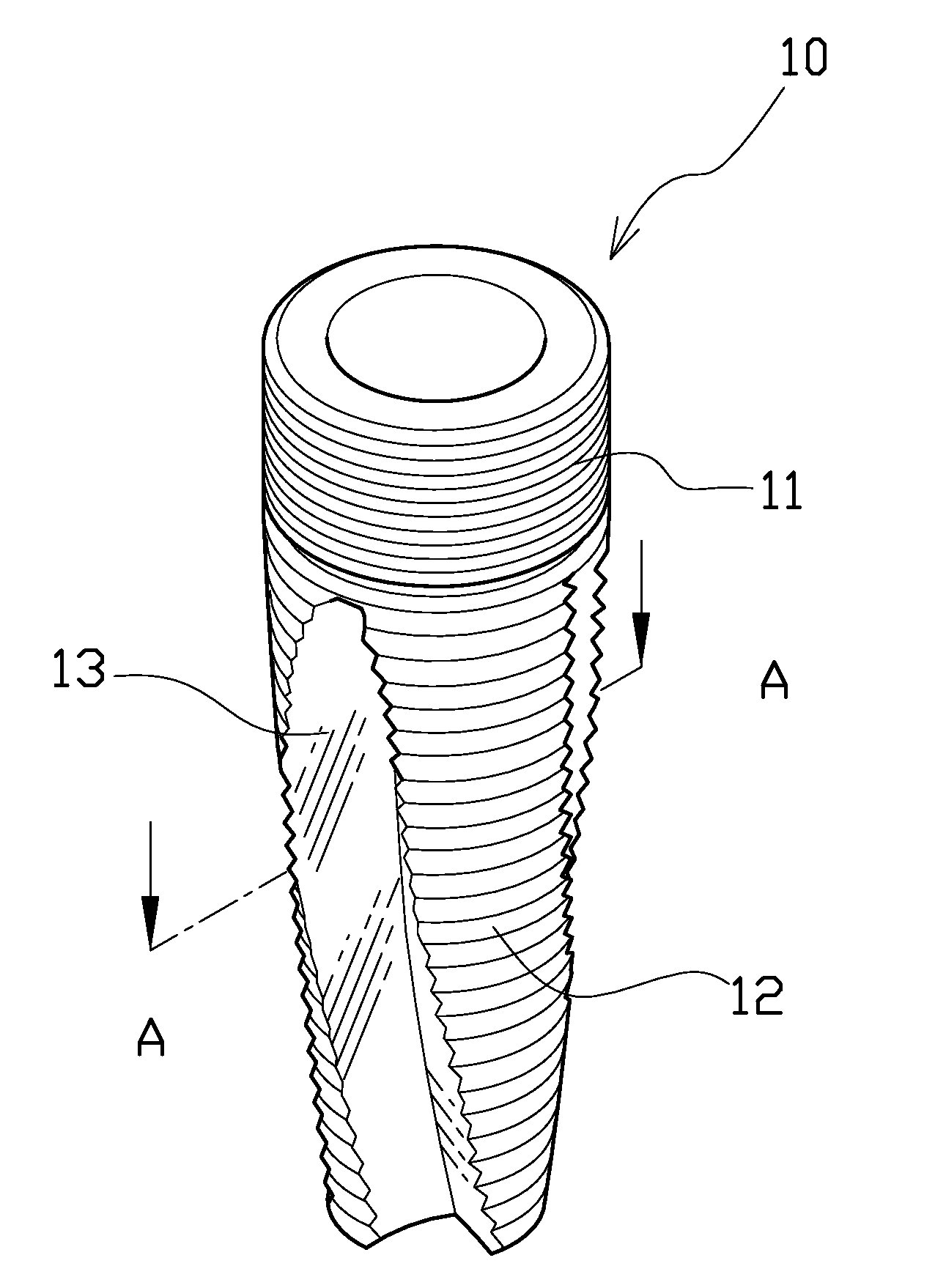
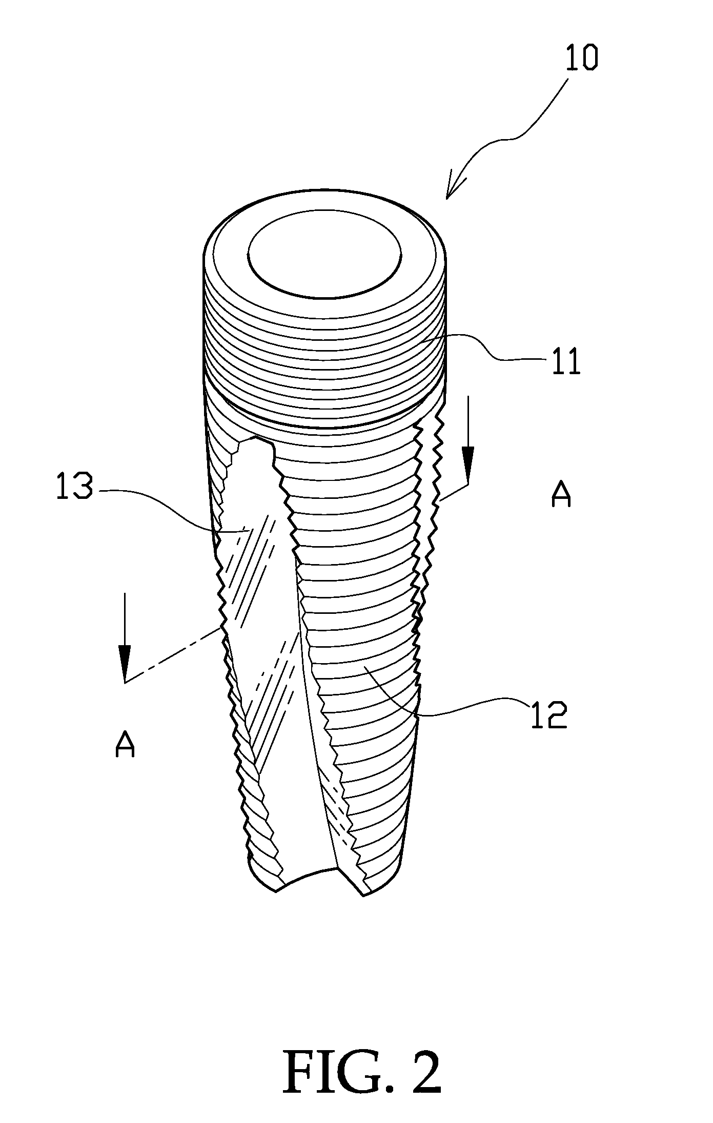
[0019]Referring to FIGS. 2 and 3 showing the present invention, wherein an implant root 10 has on its upper area a connecting portion 11, the connecting portion 11 has on its outer surface a fine threaded portion, and the implant root 10 has on its lower area a coarse threaded portion 12. The connecting portion 11 is connected with an abutment 6 of a crown such as is shown in FIG. 6; the surfaces of the coarse threaded portion 12 have sharp threads that can be implanted in a denture base of a patient by rotation.

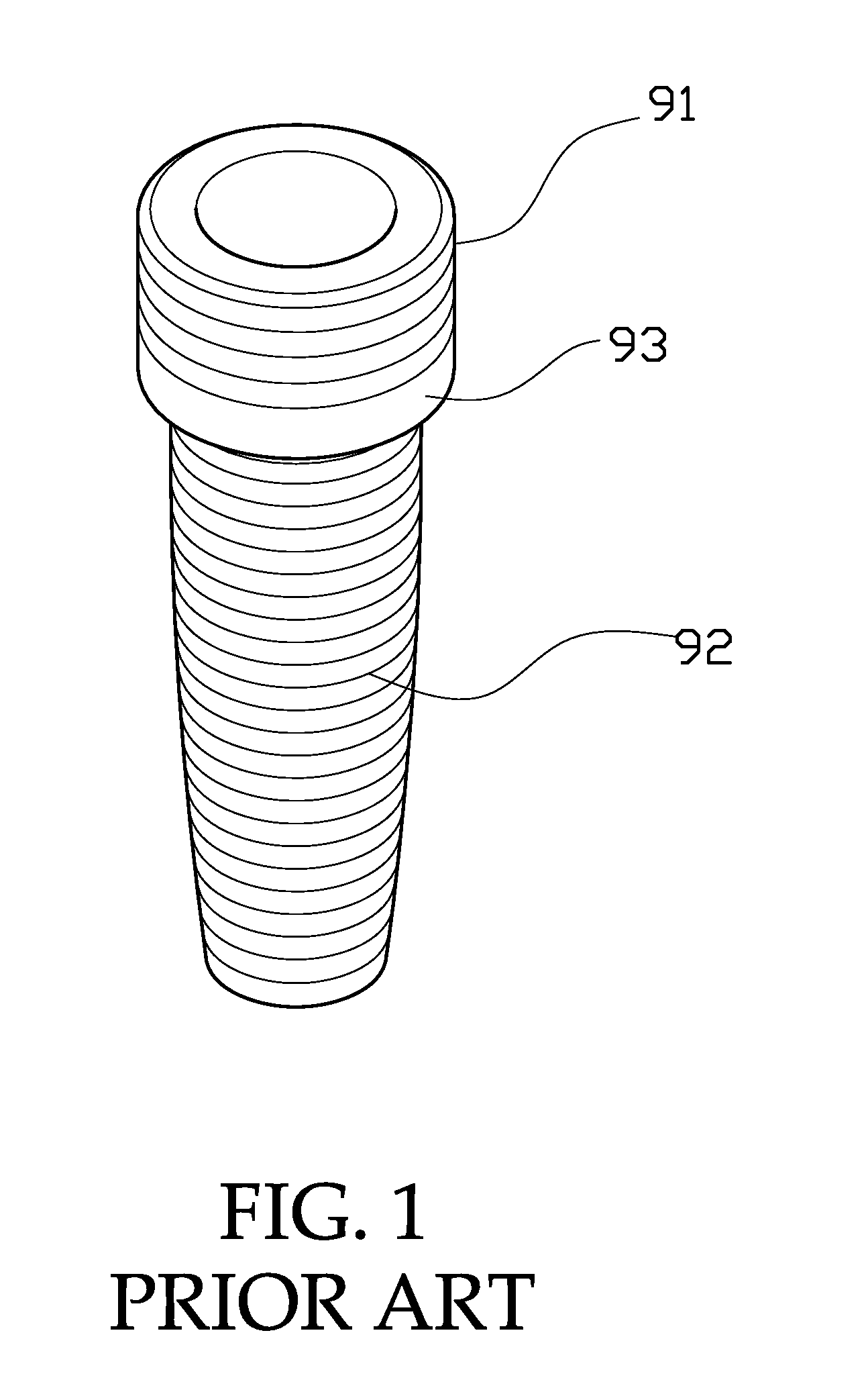
[0020]Two helical treating surfaces 13 formed on the coarse threaded portion 12 extending in the vertical direction are treated with HA coatings. Thereby the areas of the helical treating surfaces 13 are larger than the area of the conventional horizontal treating surface 93, and thereby the bone of the denture base can get fast growth to envelop the implant root 10; further by combining of the treating surfaces 13 having the HA coatings extending in the vertical direction, ...

second embodiment

[0021]Referring to FIGS. 4 and 5 showing the present invention, wherein an implant root 20 has a connecting portion 21, the connecting portion 21 has on its outer surface a fine threaded portion, and the implant root 20 has on its lower area a coarse threaded portion 22. The coarse threaded portion 22 has three arciform surfaces 23 laid out in an equiangularly spaced away mode and all extending in the vertical direction and are treated with HA coatings, the three arciform surfaces 23 are recessed arciform surfaces (referring to FIG. 5) to further increase the areas of the treating surfaces and the space for staying of the bone dusts.

[0022]Referring to FIGS. 6 and 7, the connecting portion 11 is provided with a polygonal hole 14, a screw hole 15 is provided in the bottom surface of the polygonal hole 14. Wherein the polygonal shape of the polygonal hole 14 is mated with the shape of a connecting section 61 of the abutment 6, so that the abutment 6 can be fast and correctly positioned...


PUM


Abstract

An improved implant root for tooth implanting, a coarse threaded portion of the implant root is formed to have at least two helical treating surfaces each with an HA coating (covered with hydroxyapatite) and each extending in the vertical direction. The areas of the HA coatings can thus be increased in favor of fast growth of a bone of a denture base after implanting into the bone to envelop the implant root; this can shorten the curing process from implanting the implant root to mounting a crown.

Description

BACKGROUND OF THE INVENTION[0001]1. Field of the Invention[0002]The present invention relates to an improved implant root for tooth implanting, and especially to an implant root of which a coarse threaded portion is formed to have at least two helical treating surfaces each with an HA coating and each extending in the vertical direction.[0003]2. Description of the Prior Art[0004]The history of the technique of tooth implanting in an oral cavity has been several decades of years; the technique mainly has a tooth on a denture base of a patient pulled out, then an implant root made of metal is implanted into the bone of the denture base of the patient; after the bone grows to envelop the implant root, the tooth implanting work is completed when the implant root is covered with a crown. The advantage of the work is the saving of abrading the true tooth that can solely support and fix the crown. And the false tooth implanted has increased biting force and holding force that reduce inconv...

Claims


Application Information

Patent Timeline
Patent Type & Authority Applications(United States)
IPC IPC(8): A61C8/00
CPCA61C8/0022A61C8/0012
Inventor CHEN, CHUN-LEON
Owner CHEN CHUN LEON
Why Eureka
Try Eureka