Apparatus and method for anterior intervertebral spinal fixation and fusion

Active Publication Date: 2008-06-05
INT SPINAL INNOVATIONS +2
View PDF30 Cites 153 Cited by
  • Summary
  • Abstract
  • Description
  • Claims
  • Application Information

AI Technical Summary

Benefits of technology

[0007]Device for reconstruction, fixation and bone fusion through anterior approach to the human spine. This device enables rigid fixation in all planes of motion including extension of the spine, it possesses struc

Problems solved by technology

Articulations between bony vertebras of human spine frequently deteriorate with age or trauma and become a source of pain.
They are not able to restrict movement between

Method used


Image

  • Apparatus and method for anterior intervertebral spinal fixation and fusion
  • Apparatus and method for anterior intervertebral spinal fixation and fusion
  • Apparatus and method for anterior intervertebral spinal fixation and fusion

Examples


Example

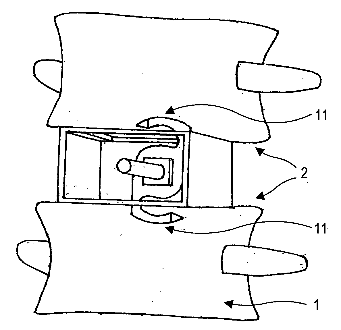
[0008]The implant consists of the outer structure or shell which is designed to conform to the disk space, provide openings for bony ingrowths and maintain the disk height by providing adequate structural strength and sufficient weight bearing surface. The shell contains a shaft which runs through its central axis from the back to the front and is fixed to the shell (FIG. 7).

[0009]In the preferred embodiment the shell is impacted into the disk space (FIG. 14) using the shell introducer (FIG. 15). Introducer fits tightly to the sides of the shell but is open in the center to allow for blades (FIG. 13).

[0010]Once the shell is placed in a correct position, individual blades (FIG. 11) are selected, mounted onto the introducer (FIG. 15) and threaded onto the shaft in horizontal orientation (FIG. 16). The blade is placed as deep as it can go and then rotated into vertical orientation breaking the endplate and hooking into the vertebra (FIG. 17). Blades alternate between clockwise and coun...


PUM


Abstract

A spinal fixation and fusion device that includes a housing with leading deep surface conforming to the posterior aspect of the intervertebral disk and trailing outer surface conforming to the anterior surface of the disk, weight bearing sides and the top and bottom surfaces with plurality of openings enabling ingrowths of bone. The device further includes a shaft running from the center of the deep surface and perpendicular to the deep surface of the housing to the center of the outer surface of the housing and affixed at least to the deep surface of the housing, and a flat metal member threaded onto the shaft with sharp leading edge which upon clockwise or counterclockwise rotation about the axis of the shaft will break the endplate, hook into the vertebra and rigidly secure the vertebra to the entire device preventing separation of the vertebra from the device during spinal motion.

Description

FIELD OF INVENTION[0001]This invention relates to a spinal fusion device. More specifically, the present invention relates to an implant and fixation device used to reconstruct spinal disk space and facilitate fusion across spinal disk apace.BACKGROUND[0002]Articulations between bony vertebras of human spine frequently deteriorate with age or trauma and become a source of pain. Spinal disk is one of these articulations and with aging process it loses its normal consistency and volume and collapses allowing for abnormal painful motion within the anterior spinal column. Spinal disk is a complex cylindrical weigh-bearing fibrous structure with non-compressible viscous center. Disk articulates with bony vertebra above and below through a large surface area circular interface known as an endplate (FIG. 1). Endplate is a thin (1-3 mm) approximately round 2-4 cm in diameter plate of dense bone and cartilage accounting for majority of the vertebral weight-bearing capacity (FIG. 2).[0003]Sur...

Claims


Application Information

Patent Timeline
IPC IPC(8): A61B17/58A61F2/44
CPCA61F2/446A61F2/447A61F2/4611A61F2002/30365A61F2220/0033A61F2002/30841A61F2002/30845A61F2002/4475A61F2002/4627A61F2002/30579A61F2220/0016A61F2002/30593A61F2/4425A61F2002/4445
Inventor AFERZON, JOSEPHAFERZON, JOSHUA MICHAEL
Owner INT SPINAL INNOVATIONS
Why Eureka
Try Eureka