
Scan Test Data Compression Method And Decoding Apparatus For Multiple-Scan-Chain Designs

a data compression and data compression technology, applied in the direction of electronic circuit testing, measurement devices, instruments, etc., can solve the problems of increasing the complexity of the system-on-chip (soc) design, increasing the amount of related test data, and limited number of test patterns that can be generated, so as to achieve the effect of effectively overcoming the problem

Inactive Publication Date: 2008-06-05
IND TECH RES INST
View PDF11 Cites 8 Cited by
  • Summary
  • Abstract
  • Description
  • Claims
  • Application Information

AI Technical Summary

Benefits of technology

The present invention provides a scan test data compression method and decoding apparatus for multiple-scan-chain designs. This method can effectively overcome the problem in conventional test data compression techniques. The scan test data compression method can transform the scan test pattern into an encoded data, and use a decoder circuit to decode the encoded data. The amount of encoded data is much less than the original data, and the data transmission time is reduced. The decoder includes a controller, a decoding buffer, and a switching box. The encoded data is transmitted to the scan chains of the circuit-under-test (CUT) for testing. The decoding buffer reduces the internal changes in the scan flip-flop by repetitively sending the same bit slice to CUT, and further reduces the power consumption for testing. The decoding apparatus is simple, flexible, and can be used in a conventional design flow or integrated into ATPG to provide higher efficiency. The hardware cost of the decoder is inexpensive, and without the problem of fault coverage loss.

Problems solved by technology

As the very large scale integrated circuit (VLSI) technology rapidly grows, the complexity of system-on-chip (SoC) design increases, and the amount of related test data also increases greatly.
Therefore, the number of test patterns that can be generated is limited.
Even if the automatic test pattern generator (ATPG) can find the test pattern to detect faults, the decoder may not be able to generate corresponding test pattern, and thus result in fault coverage loss.
This method also randomly fills the unspecified bits to generate test pattern, which causes a large amount of power consumption.
This type is more flexible so that it has a higher compression rate than the first type, but has the same disadvantages of high power consumption and fault coverage loss because of the limitation of the decoder.
This type may result in the synchronization overhead with the tester due to the mismatch between the tester's transmission speed and the decoding speed.
This type is not convenient in supporting multiple-scan-chain designs.
The bit-flip design must concern the hardware area, especially for the RAS, which may be considerably expensive.

Method used


Image

  • Scan Test Data Compression Method And Decoding Apparatus For Multiple-Scan-Chain Designs
  • Scan Test Data Compression Method And Decoding Apparatus For Multiple-Scan-Chain Designs
  • Scan Test Data Compression Method And Decoding Apparatus For Multiple-Scan-Chain Designs

Examples


Embodiment Construction

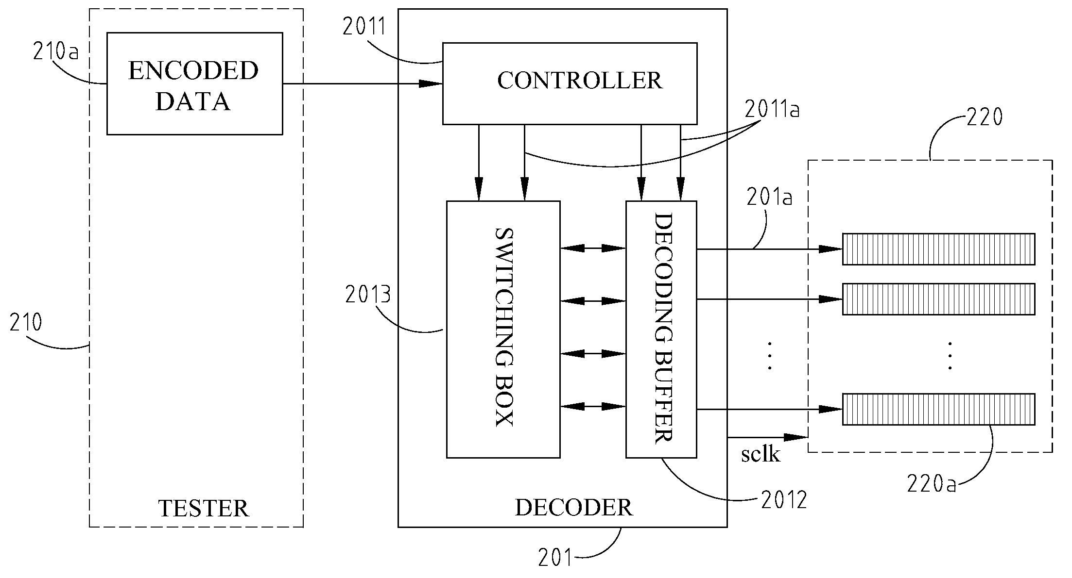
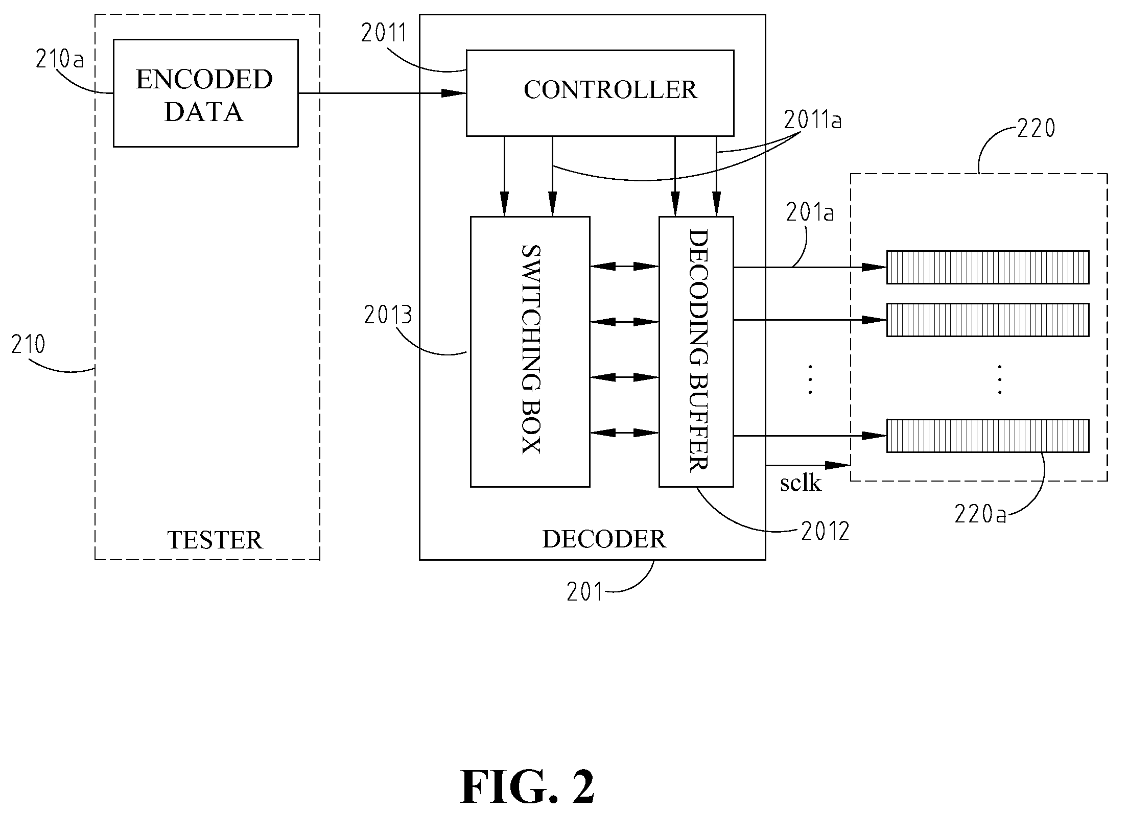
[0025]FIG. 2 shows a structure of a decoding apparatus for scan test data of a multiple-scan-chain design, and the applied scan test environment thereof. As shown in FIG. 2, the decoding apparatus for scan test data comprises a decoder 201, connected to an external tester 210. The decoder 201 further includes a decoding buffer 2012, a controller 2011 and a switching box 2013.

[0026]An external tester 210 inputs an encoded data 210a to the decoder 201. The controller 2011 of the decoder 201 generates a plurality of control signals 2011a for switching box 2013 and decoding buffer 2012 according to input encoded data 210a. Based on the control signals 2011a, the decoder 201 uses a decoding algorithm, through controlling shift and copy modes, to decode the encoded data 210a, asserts the scan clock sclk of a CUT 220, and transmits the decoded data 201a through the decoding buffer 2012 to the multiple scan chains 220a of the CUT 220 for testing.

[0027]The decoding buffer 2012 is configured ...


PUM


Abstract

Disclosed is a scan test data compression method and decoding apparatus for multiple-scan-chain designs. The apparatus comprises a on-chip decoder connected to a tester. The decoder includes a decoding buffer configured as a multilayer architecture, a controller, and a switching box for receiving a shift signal or a copy signal. The decoding buffer is used to store decoded test data. While the decoder decodes the encoded data, it transmits control signals to both the decoding buffer and the switching box from the controller, and sends the decoded data to scan chains of a CUT for testing through the decoding buffer. This invention has the advantages of simple encoding method, high compression rate, low power consumption in testing, and without the fault coverage loss.

Description

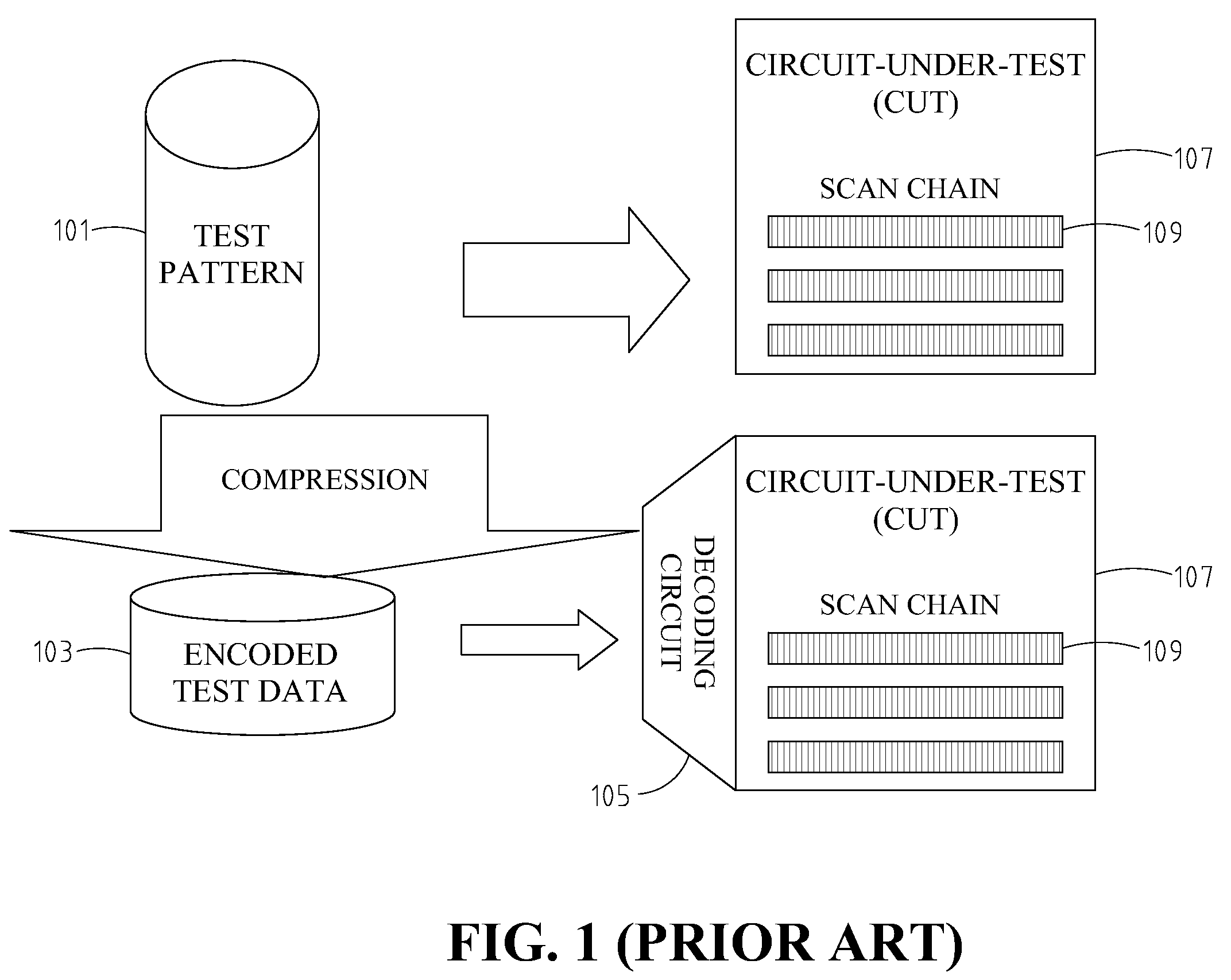
FIELD OF THE INVENTION[0001]The present invention generally relates to a scan test data compression method and decoding apparatus, applicable to multiple-scan-chain designs.BACKGROUND OF THE INVENTION[0002]As the very large scale integrated circuit (VLSI) technology rapidly grows, the complexity of system-on-chip (SoC) design increases, and the amount of related test data also increases greatly. To prevent the test cost from increasing caused by large amount of data, numerous test data compression methods have been proposed. As shown in FIG. 1, these compression methods first compress / encode test pattern 101 into encoded test data 103, and then use an embedded decompressor / decoder 105 to decode the encoded data for transmission to scan chains 109 of circuit-under-test (CUT) 107 for test. The input data of the decoder comes from the tester, and its outputs are connected to scan chains. The number of the inputs of the decoder is usually less than the number of outputs, and thus few in...

Claims


Application Information

Patent Timeline
Patent Type & Authority Applications(United States)
IPC IPC(8): G01R31/28
CPCG01R31/3016G01R31/31727G01R31/31725
Inventor LIN, SHIH-PINGLEE, CHUNG-LENCHEN, JWU E.CHEN, JI-JANLUO, KUN-LUNWU, WEN-CHING
Owner IND TECH RES INST
Learn More