
System of smart colloidal dampers with controllable damping curves using magnetic field and method of using the same

a magnetic field and damping curve technology, applied in the field of colloidal dampers, smart dampers, ferrofluid, semi-active vibration control, can solve the problems of material failure, rubber material failure, material failure,

Active Publication Date: 2008-06-12
RGT UNIV OF CALIFORNIA
View PDF31 Cites 17 Cited by
  • Summary
  • Abstract
  • Description
  • Claims
  • Application Information

AI Technical Summary

Benefits of technology

[0030]The host structure may be a vehicle, and the method further comprising the steps of providing dampers as shock absorbers installed on the vehicle to isolate it from vibration, measuring the vibrations, communicating the measured vibrations to a control circuit, where a control strategy is stored, referring to the measured vibrations and a vibration history to generate a corresponding plurality of command signals to a corresponding plurality of pow

Problems solved by technology

The key factor to reduce the durability of current dampers is the failure of rubber materials used for seal purpose.
The higher temperature will derogate rubber materials used in dampers and cause material failure.
In addition, temperature change also derogates the damping capacity of damping medium in dampers.
Besides heat generation, current hydraulic dampers possess low damping efficiency, which is defined by the ratio of the dissipated energy per cycle and the input energy during loading phase.
The reason is that inner pressure inside the dampers reduces the effective area of damping forces.
However, utilization of such valves makes damping curves unsmooth or ragged and increases the fabrication cost of dampers.
However, currently, such dampers, e.g., magnetorheological fluid (MRF) dampers, are primarily hydraulic dampers, which dissipate energy by an internal friction mechanism (viscosity) of the fluid passing through orifices.
Thus, they also convert all external energy into heat and they have all the above disadvantages of hydraulic dampers.

Method used


Image

  • System of smart colloidal dampers with controllable damping curves using magnetic field and method of using the same
  • System of smart colloidal dampers with controllable damping curves using magnetic field and method of using the same
  • System of smart colloidal dampers with controllable damping curves using magnetic field and method of using the same

Examples


Embodiment Construction

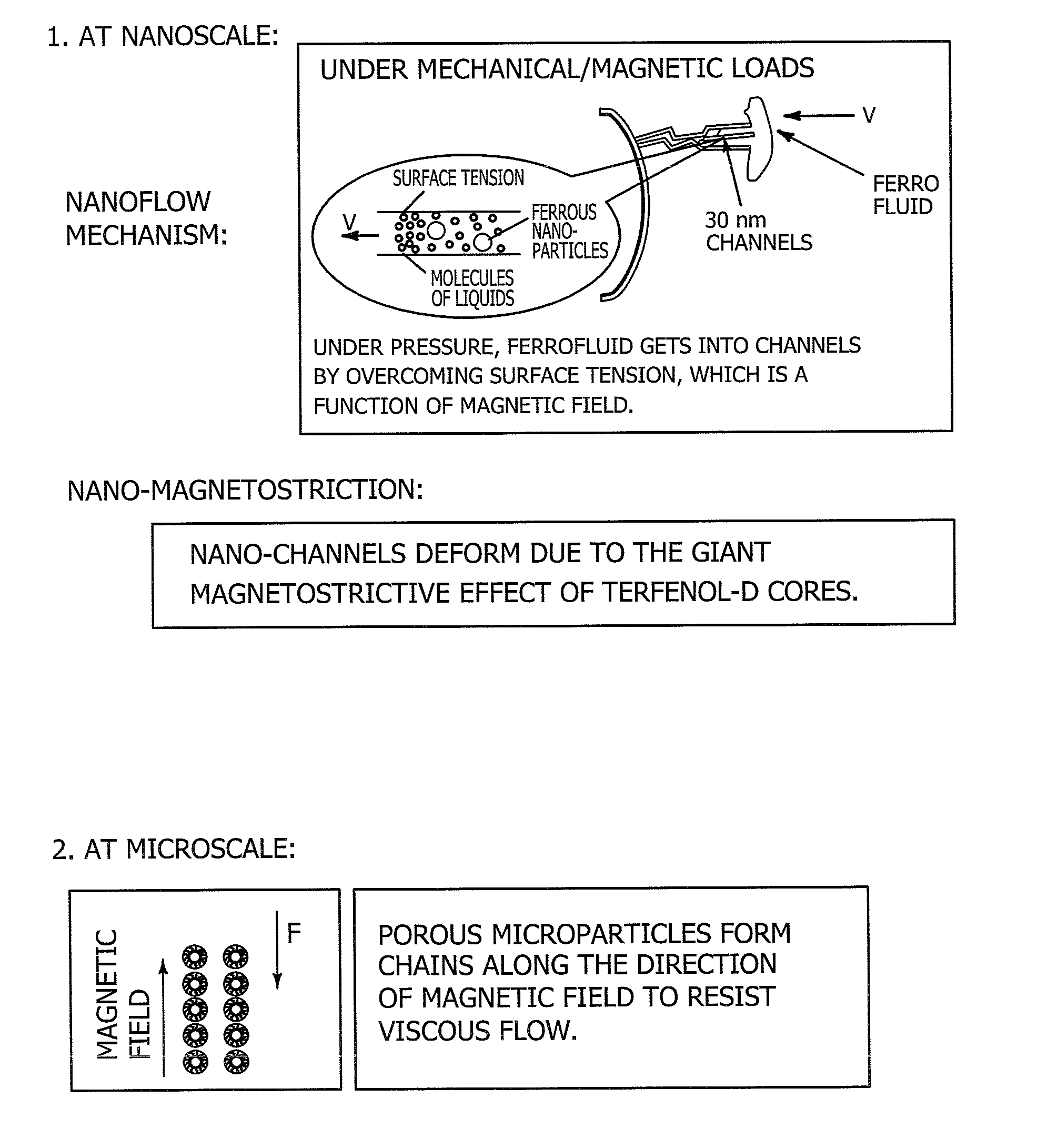
[0046]What is disclosed is a type of colloidal damping media with on-demand controllable loss-factor and a methodology to utilize the damping media for the development of colloidal dampers with on-demand controllable damping forces.

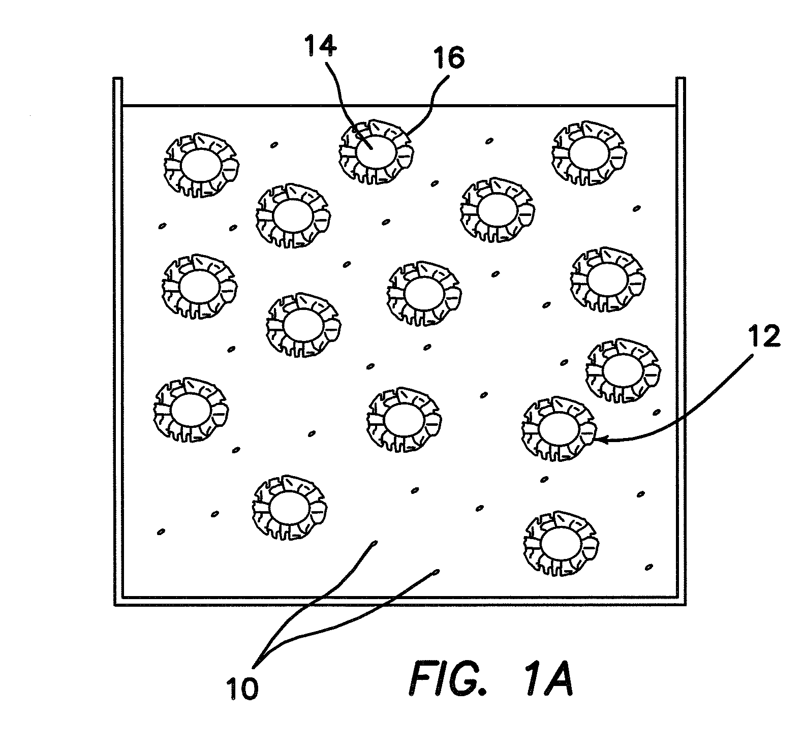
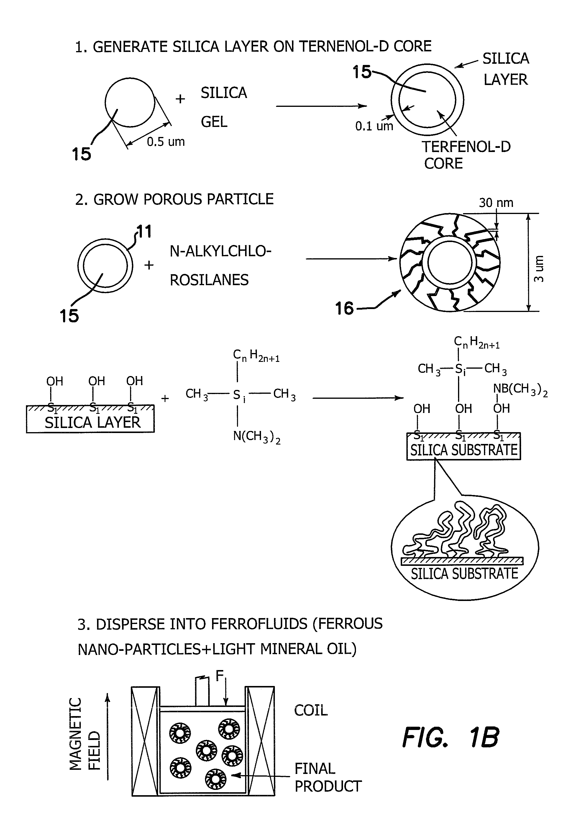
[0047]In one embodiment as shown in the diagram of FIG. 1a the damping medium is composed of water-based ferro-fluids 12, which is mixture of nanometer-sized ferrous particles 10 (not shown) and distilled water, and micrometer-sized porous silica particles 16, which collectively comprise the damping material or fluid 36. The porous particles 16 are prepared by reacting n-alkylchlorosilanes with small silica cores 14 sold by Mallinckrodt Baker, Inc., Phillipsburg N.J., http: / / www.mallbaker.com / , under the product name Bakerbond Wide-Pore Octadecyl (C18) Prep LC Packing. The chemical procedure to synthesize such porous particles 16 is the interaction of hydroxyl-containing silica with organosilicon compounds of the formula R4−nSiXn, where X is Cl, OCH3, OC2...


PUM

PropertyMeasurementUnit
Lengthaaaaaaaaaa
Temperatureaaaaaaaaaa
Magnetic fieldaaaaaaaaaa

Abstract

An apparatus includes a damper, a source of magnetic field coupled to the damper, a colloidal ferro-fluidic damping medium disposed in the damper, a sensor installed on the host structure to measure vibrations, and a vibration control circuit. The output of the sensor is fed back to the control circuit, which outputs a command signal to the source of the magnetic field applied to the damper to change the magnetic field in the damper as well as its damping curve so that the dynamic performance of the host structure installed with the damper is changed automatically to yield maximum vibration mitigation.

Description

RELATED APPLICATIONS[0001]The present application is related to U.S. Provisional Patent Application Ser. No. 60 / 873,841, filed on Dec. 8, 2006, which is incorporated herein by reference and to which priority is claimed pursuant to 35 USC 119.BACKGROUND OF THE INVENTION[0002]1. Field of the Invention[0003]The invention is directed to colloidal dampers, smart dampers, ferro-fluid, semi-active vibration control.[0004]2. Description of the Prior Art[0005]The key factor to reduce the durability of current dampers is the failure of rubber materials used for seal purpose. The fundamental mechanism for current state of the art dampers to dissipate external mechanical energy is to convert it into heat. As a consequence, the temperature of current dampers rise very quickly and the dampers are operated at high temperature levels. The higher temperature will derogate rubber materials used in dampers and cause material failure. In addition, temperature change also derogates the damping capacity ...

Claims


Application Information

Patent Timeline
IPC IPC(8): F16F15/023H01F1/44
CPCH01F1/447F16F9/53
Inventor ZHOU, GANGYISUN, LIZHI
Owner RGT UNIV OF CALIFORNIA
Learn More