
Ignition anode, in particular for reignitable rocket combustion chambers

Inactive Publication Date: 2008-06-12
ASTRIUM GMBH
View PDF3 Cites 1 Cited by
  • Summary
  • Abstract
  • Description
  • Claims
  • Application Information

AI Technical Summary

Benefits of technology

[0009]The invention provides for an ignition anode for reignitable rocket combustion chambers which is less likely to become damaged by erosion on the ignition frontal area. The burn-off of the ignition frontal area with progressive igniter operation is also reduced. Furthermore, a more uniform anode burn-off over the ignition frontal area should be achieved with progressive operating time. Additionally, the chances of safer operation are increased because reignition during flight operation can be ensured because the operational risk of the igniter is minimized.
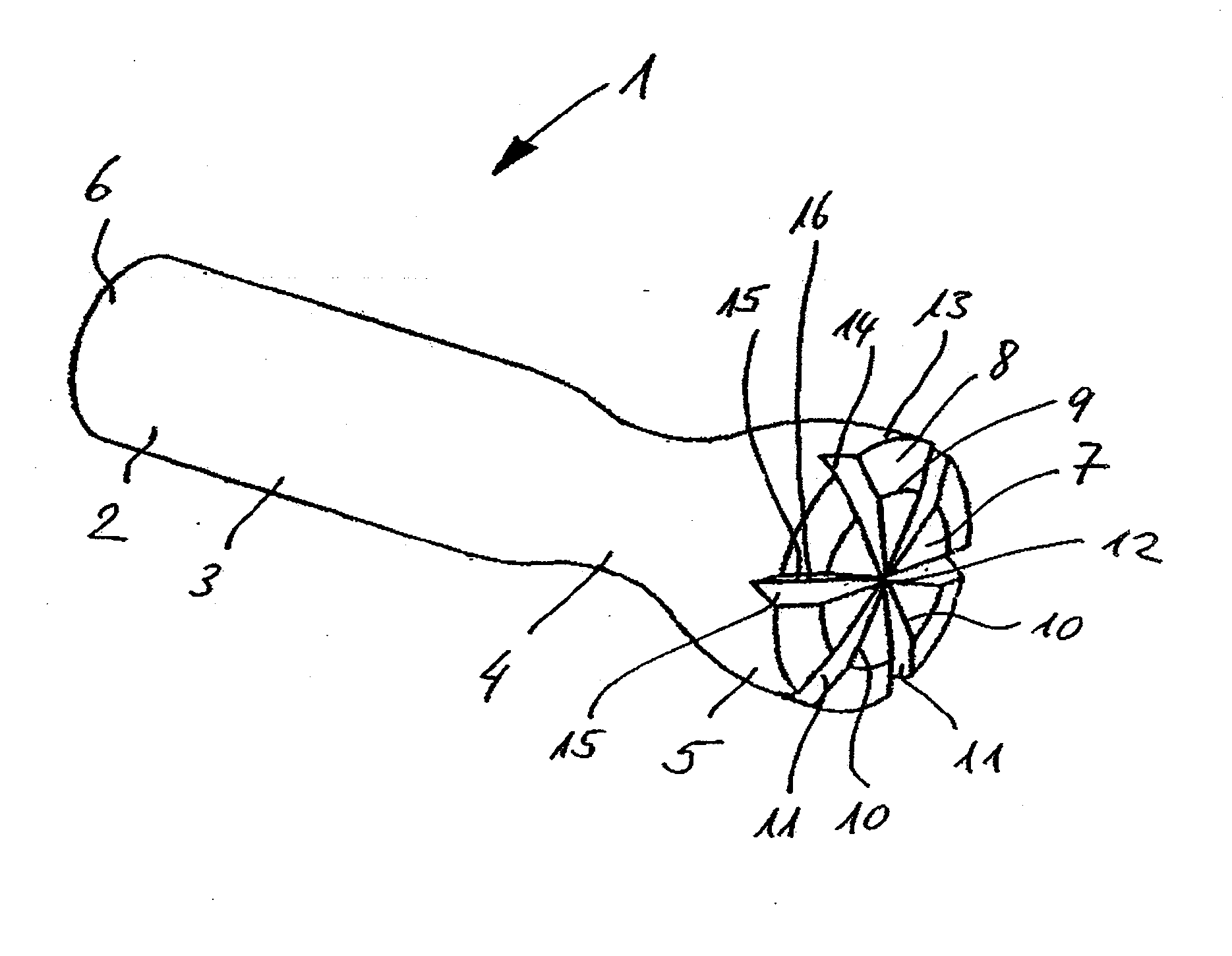
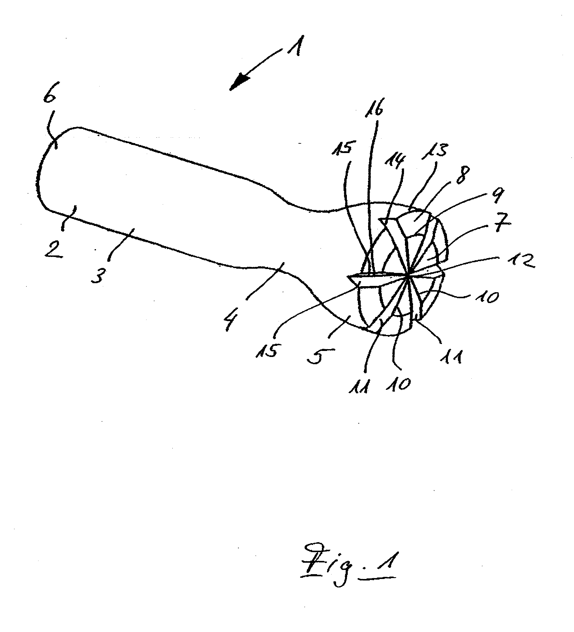
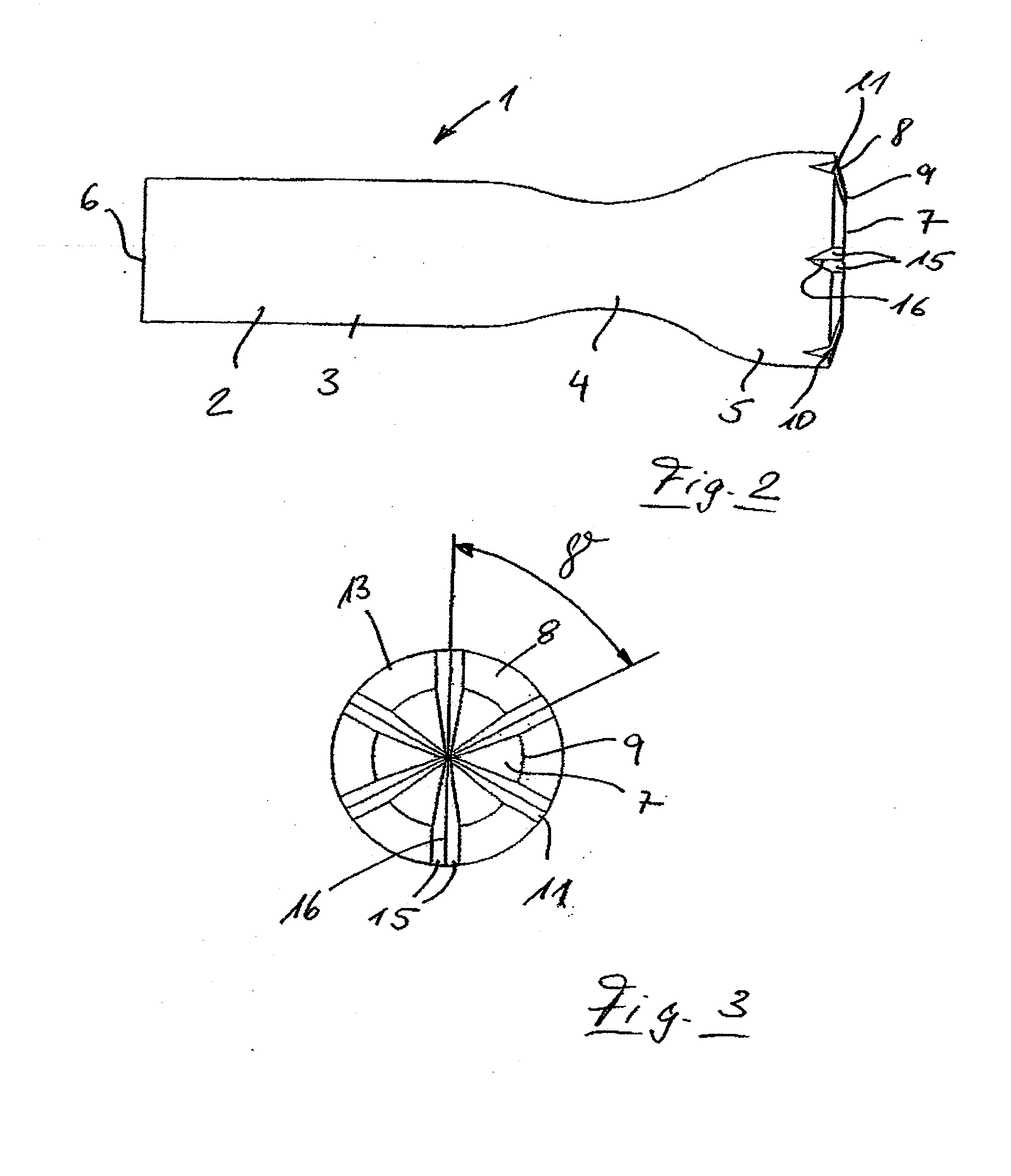
[0010]According to the invention, the so-called build-up of the plasma spark during reignition is considerably facilitated by utilizing an uneven, in particular, a sharply uneven, frontal area design on the ignition anode. In particular, the frontal area design utilizes at least one particularly sharp, burr-free edge. Such an edge can still function even if an oxide layer forms on or is present on the ignition frontal area. The reason for this relates to the fact that a plasma spark breaks down more easily on an edge, in particular, on a sharp, burr-free edge, than on a flat surface. Furthermore, it is considered advantageous to utilize a plurality (i.e., more than one) edges, which are preferably sharp edges. This ensures that the ignition spark consistently breaks down at different places on the ignition anode frontal area, and thus also provides burn-off at different points. The distribution of the points at which the ignition spark breaks down can thereby be such that the spark preferably breaks down on the edge that forms the narrowest spark gap. If an edge is somewhat worn by burn-off, another edge can form the narrowest spark gap and thereby form the edge at which the spark is most likely to arc. This makes it possible to achieve a uniform burn-off of the anode by sparking at the respectively most raised edge of the frontal area. Furthermore, an enlarged ignition frontal area is created by the irregularities formed according to the invention. A defined enlargement of the surface (compared to that of the prior art) can be achieved, in particular, by utilizing V-shaped notches. Such an arrangement results in a substantially improved spark breakdown on the edges of the notches over the operating time of the anode, and this minimizes the overall operational risk (risk of operation failure) of the igniter.

Problems solved by technology

However, a progressive erosion on the ignition frontal area is observed with a large number of reignition processes of the rocket combustion chamber.
Likewise, an increased wear is established as a result of burn-off.
Furthermore, when the rocket combustion chamber is switched off, an oxide layer forms on the ignition frontal area, which when the combustion chamber is reignited impairs the build-up of the plasma spark.
This results in a possible increased operational risk.

Method used


Image

  • Ignition anode, in particular for reignitable rocket combustion chambers
  • Ignition anode, in particular for reignitable rocket combustion chambers
  • Ignition anode, in particular for reignitable rocket combustion chambers

Examples


Embodiment Construction

[0024]The particulars shown herein are by way of example and for purposes of illustrative discussion of the embodiments of the present invention only and are presented in the cause of providing what is believed to be the most useful and readily understood description of the principles and conceptual aspects of the present invention. In this regard, no attempt is made to show structural details of the present invention in more detail than is necessary for the fundamental understanding of the present invention, the description taken with the drawings making apparent to those skilled in the art how the several forms of the present invention may be embodied in practice.

[0025]FIGS. 1-5 show a non-limiting embodiment of an ignition anode 1 which includes an ignition anode body 2 having a generally cylindrical section 3, a constricted section 4, and an anode head section 5. The anode head section 5 has a larger diameter than the cylindrical section 3. The cylindrical section 3 has a free e...


PUM


Abstract

An ignition anode for an ignition device of a reignitable rocket combustion chamber. The anode includes an ignition anode body having an ignition anode frontal area. The ignition anode frontal area has a plurality of edges. This Abstract is not intended to define the invention disclosed in the specification, nor intended to limit the scope of the invention in any way.

Description

CROSS-REFERENCE TO RELATED APPLICATIONS[0001]The present application claims priority under 35 U.S.C. §119 of German Patent Application No. 10 2006 052 171.4-23, filed on Nov. 2, 2006, the disclosure of which is expressly incorporated by reference herein in its entirety.BACKGROUND OF THE INVENTION[0002]1. Field of the Invention[0003]The invention relates to an ignition anode for, in particular, reignitable rocket combustion chambers.[0004]2. Discussion of Background Information[0005]A prior art ignition system made by Stork® Product Engineering B.V. is known by the name EGOX / GH2 VINCI EM Igniter. This is an igniter for reignitable rocket combustion chambers, whereby a gaseous hydrogen-oxygen mixture is ignited by means of electric ignition. An igniter 100 of this type is shown diagrammatically (in a longitudinal sectional view) in FIG. 6 of the instant application.[0006]As can be seen in FIG. 6, the igniter 100 has an igniter housing 101 and a spark plug device 102. An igniter inject...

Claims


Application Information

Patent Timeline
IPC IPC(8): H01T13/20
CPCF02K9/95F02K9/94
Inventor UNRATH, DIETER
Owner ASTRIUM GMBH
Learn More