Light-Emitting Element Light Source and Temperature Management System Therefor

a technology of light-emitting elements and temperature management systems, applied in the field of light-emitting elements, can solve the problems of reducing the life and/or operating efficiency of leds, affecting the operation efficiency of light-emitting elements, and unable to monitor the operating temperature of light-emitting elements

Inactive Publication Date: 2008-06-12
KONINKLIJKE PHILIPS ELECTRONICS NV
View PDF12 Cites 39 Cited by
  • Summary
  • Abstract
  • Description
  • Claims
  • Application Information

AI Technical Summary

Benefits of technology

[0011]An object of the present invention is to provide a light-emitting element light source and temperature management system therefor. In accordance with an aspect of the present invention, there is provided a light source, comprising: a substrate comprising a substantially thermally isolated probe; a light-emitting element operatively mounted to said substrate thermally coupled to said probe; a temperature sensing element for sensing an operating temperature of said light-emitting element via said probe; and a driving system operatively coupled to said temperature sensing element and said light-emitting element, said driving system configured to provide one or more control signals to the light-emitting element, said one or more control signals configured at least in part using said sensed operating temperature.

Problems solved by technology

Such changes in LED temperature may lead to wavelength shifts, flux variations and other such generally undesirable effects.
Furthermore, when driving LEDs at high currents (e.g., high brightness LEDs), for instance to maximise an output of the light source, the LED temperature may rise significantly, which may lead to a reduction in LED lifetime and / or operating efficiency.
Such heat extraction techniques, while providing means for extracting heat form the light source's LEDs, do not enable monitoring of the light-source's operating temperature, which may be used to fine tune the operational parameters of the light source.
While the temperature of the heatsink / substrate can be monitored, changes in the temperature of the LED(s) will have a delayed effect on the temperature of the heatsink / substrate, due in part to the large thermal mass of the heatsink / substrate relative to each LED chip.
Such delays may lead to a delayed reaction of the monitoring system, and thereby allow for undesirable thermal effects to occur.
Furthermore, the different temperatures of multiple LEDs may not be determined independently.
In general, the above and other such thermal management methods provide poor or unsatisfactory results, mostly attributed, at least in part, to their configurations relating to measurement of the LED operating temperature.

Method used


Image

  • Light-Emitting Element Light Source and Temperature Management System Therefor
  • Light-Emitting Element Light Source and Temperature Management System Therefor
  • Light-Emitting Element Light Source and Temperature Management System Therefor

Examples


example 1

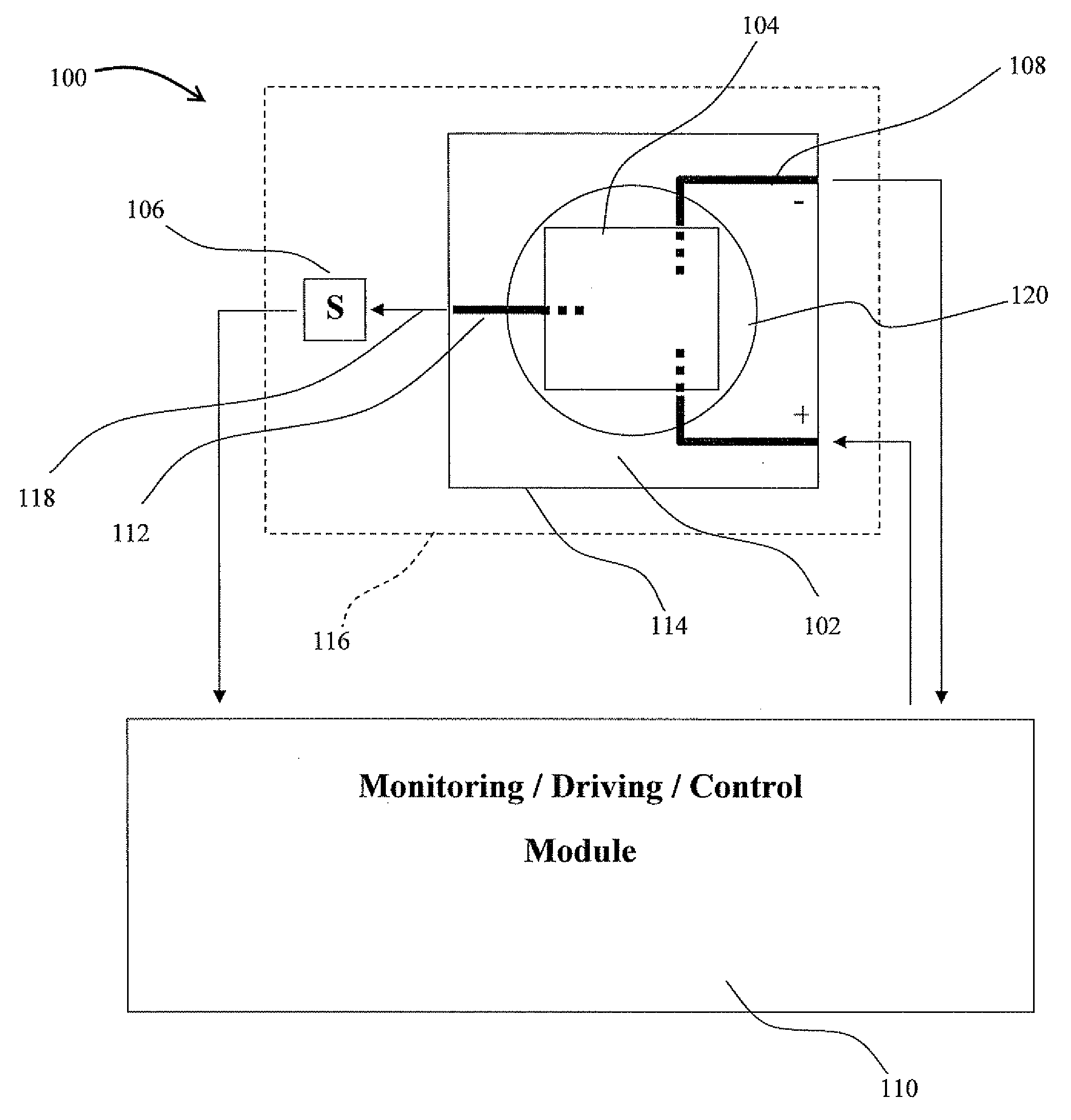
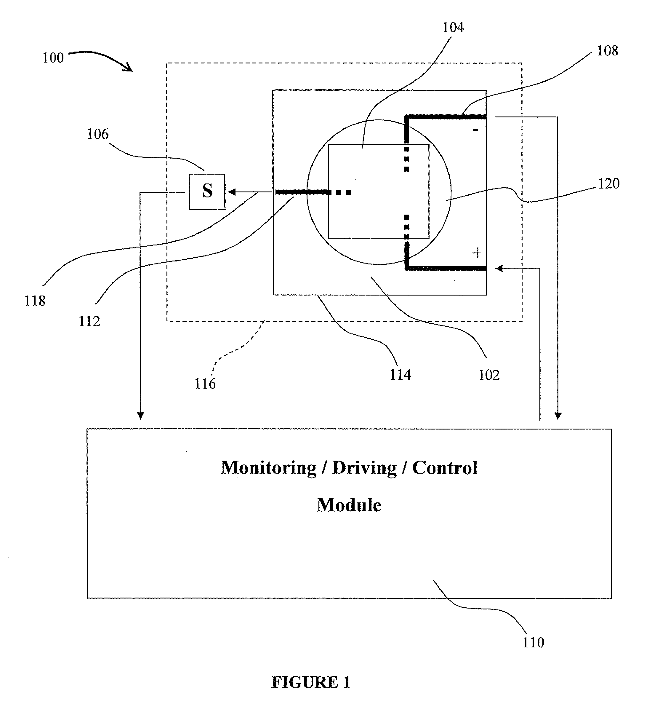
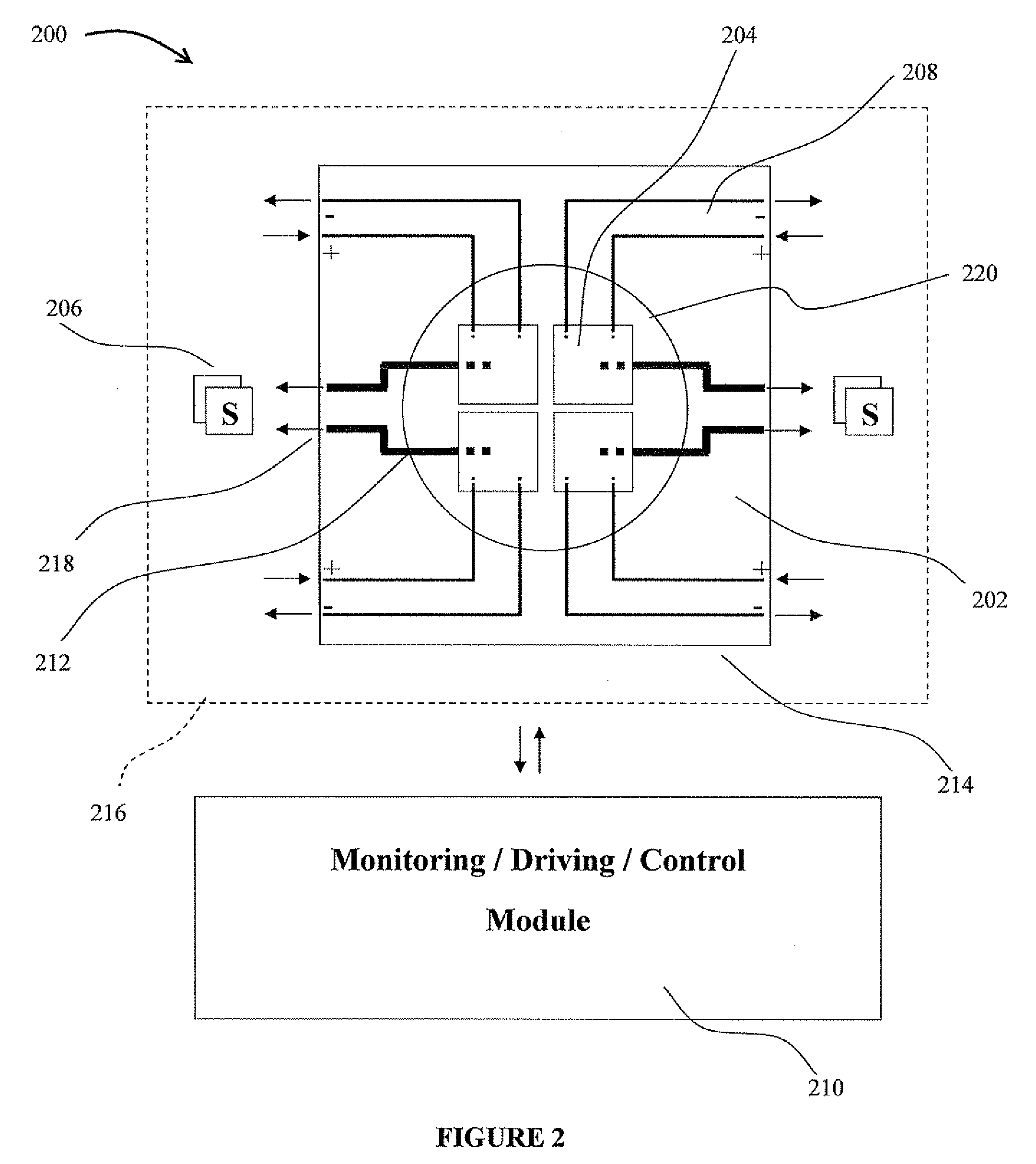
[0065]Referring now to FIGS. 4 and 5, a light source, generally referred to using the numeral 400, and in accordance with one embodiment of the present invention, will now be described. The light source 400 generally comprises a substrate 402 and four light-emitting elements, as in elements 404, mounted thereto. The light source 400 further comprises four temperature sensing elements, as in elements 406, for sensing an operating temperature of each of the light-emitting elements 404.

[0066]In particular, the top face of the substrate 402 comprises a segment (not shown) of drive circuitry 408 operatively coupled to the light-emitting elements 404 and leading to a light source driving mechanism (not shown) configured to impart a drive current to the light-emitting elements 404. The top face of the substrate 402 further comprises thermal probes 412 (FIG. 5) thermally coupling each light-emitting element 404 to a respective temperature sensing element 406. A monitoring, driving and contr...

example 2

[0074]Referring now to FIGS. 6 and 7, a light source, generally referred to using the numeral 500, and in accordance with one embodiment of the present invention, will now be described. The light source 500 generally comprises a substrate 502 and four light-emitting elements, as in elements 504, mounted thereto. The light source 500 further comprises four temperature sensing elements, as in elements 506, for sensing an operating temperature of each of the light-emitting elements 504.

[0075]In particular, the top face of the substrate 502 comprises a segment (not shown) of drive circuitry 508 operatively coupled to the light-emitting elements 504 and leading to a light source driving mechanism (not shown) configured to impart a drive current to the light-emitting elements 504. The top face of the substrate 502 further comprises thermal probes 512 thermally coupling each light-emitting element 504 to a respective temperature sensing element 506. A monitoring, driving and control module...

example 3

[0084]FIGS. 8 and 9 provide different mounting structures 616 and 716 for use in mounting respective light-emitting element packages 614 and 714 similar to those described hereinabove with reference to FIGS. 4 to 7. In the example of FIG. 8, the slots 626 are generally arcuate in nature defining a substantially oblong flexible region 628. In the example of FIG. 9, the slots 726 are L-shaped, defining as in FIG. 6, a square or rectangular flexible region 728. Other slot shapes and configurations providing similar advantages should be apparent to the person skilled in the art and are thus not meant to depart from the general scope and nature of the present disclosure.


PUM


Abstract

The present invention provides a light-emitting element light source comprising a system for sensing, and optionally managing, an operating temperature of the light source. In general, the light source comprises one or more light-emitting elements, which may be arranged in one or more groups, one or more arrays or one or more clusters thereof, operatively mounted to respective and/or common substrates. The one or more substrates each generally comprise circuitry operatively coupling the light-emitting element(s) mounted thereto to a light source driving mechanism configured to impart a drive current to the light-emitting element(s). The substrate(s) also comprises one or more thermal probes configured to thermally couple one or more respective and/or combinations of selected light-emitting elements to one or more temperature sensing elements such that an operating temperature of the selected light-emitting element(s) may be sensed, monitored, and optionally controlled in order to maintain desirable light source operating and/or output characteristics.

Description

FIELD OF THE INVENTION[0001]The present invention pertains to the field of lighting and in particular to a light-emitting element light source and temperature management system therefor.BACKGROUND[0002]Advances in the development and improvements of the luminous flux of light-emitting devices such as solid-state semiconductor and organic light-emitting diodes (LEDs) have made these devices suitable for use in general illumination applications, including architectural, entertainment, and roadway lighting. Light-emitting diodes are becoming increasingly competitive with light sources such as incandescent, fluorescent, and high-intensity discharge lamps. Also, with the increasing selection of LED wavelengths to choose from, white light and colour changing LED light sources are becoming more popular.[0003]In general, these light sources comprise one or more LED packages each comprising a substrate to which one or more LEDs are mounted. As the ambient temperature changes, or as the power...

Claims


Application Information

Patent Timeline
Patent Type & Authority Applications(United States)
IPC IPC(8): H01K1/62H05B44/00
CPCH05B33/0872H05B33/0821H05B45/18H05B45/28H05B45/20H05B45/40
Inventor SCHMEIKAL, LAWRENCE
Owner KONINKLIJKE PHILIPS ELECTRONICS NV
Why Eureka
Try Eureka