Method for detecting abnormality of temperature sensor in machine tool

a technology of temperature sensor and machine tool, which is applied in the direction of liquid/fluent solid measurement, fluid pressure measurement, electric devices, etc., can solve the problems of abnormal temperature sensor, increased machining dimensional error, and inability to perform normal correction, etc., and achieve cost reduction

Inactive Publication Date: 2008-06-12
OKUMA CORP
View PDF0 Cites 10 Cited by
  • Summary
  • Abstract
  • Description
  • Claims
  • Application Information

AI Technical Summary

Benefits of technology

[0011]According to the present invention, the determination of the abnormality of the detected temperature becomes possible only with a temperature sensor used for a correction and a temperature measuring device. Accordingly, it is not necessary to use extra temperature sensors and temperature measuri

Problems solved by technology

In the above-mentioned conventional method, when an abnormal temperature due to disconnection or short circuit in the temperature sensor, or failure of the temperature measuring device is detected, a normal correction may not be performed and the machining dimensional error may increase.
Further, the moving body of the machine may collide with a workpiece due to an abnormal correction amount, so that the abnormality of the temperature sensor should be detected.
However, the abnormality or the li

Method used


Image

  • Method for detecting abnormality of temperature sensor in machine tool
  • Method for detecting abnormality of temperature sensor in machine tool
  • Method for detecting abnormality of temperature sensor in machine tool

Examples


Embodiment Construction

[0020]An embodiment of the present invention will hereinafter be described based on the drawings.

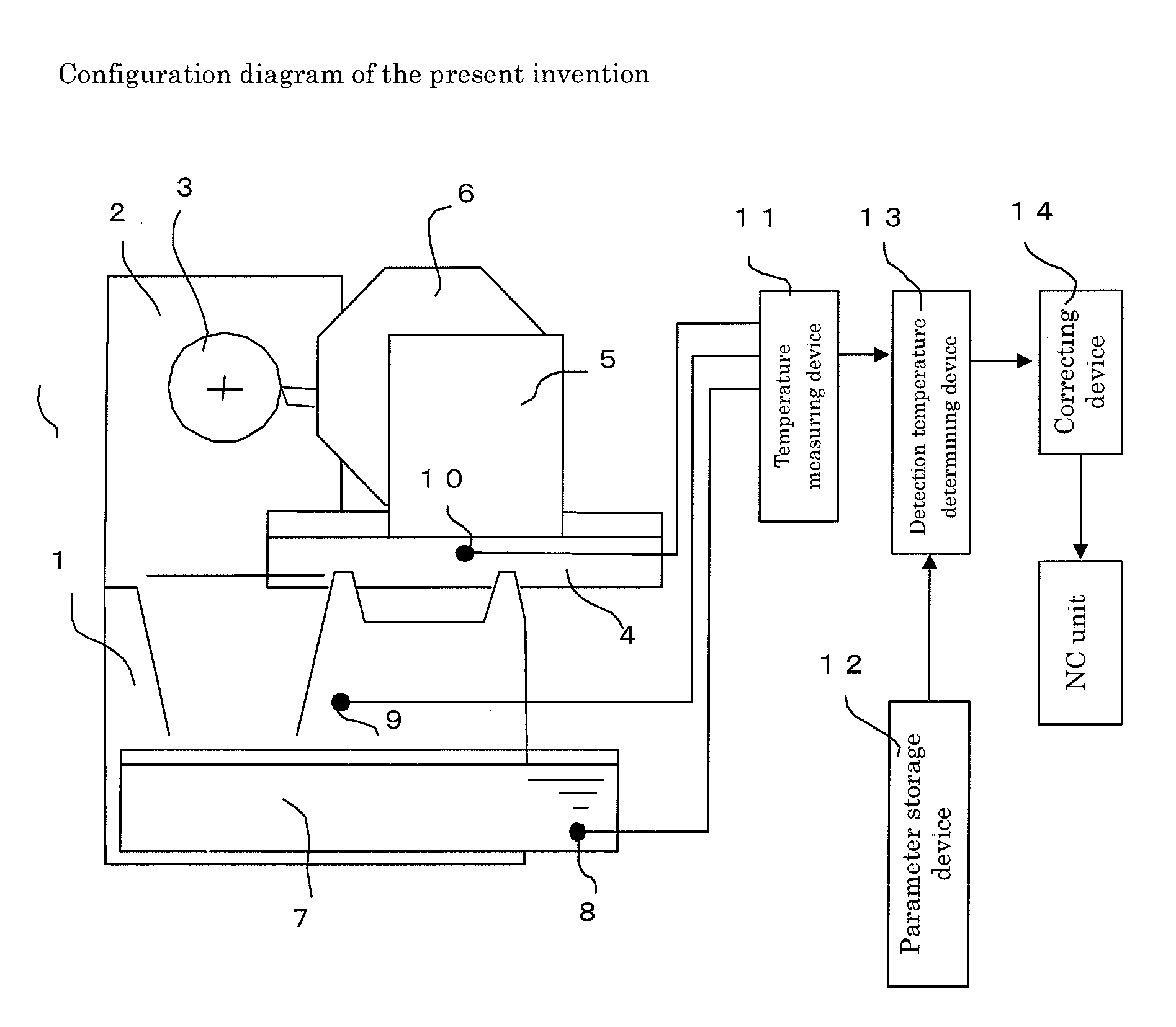
[0021]FIG. 1 is a schematic diagram of a lathe as one example of a machine tool as viewed from an axial direction of a main spindle. A main spindle stock 2 is securely installed on a left-hand upper surface of a bed 1, and a chuck 3 is also securely installed on the main spindle projected from the main spindle stock 2 to thereby enable a work to be held. A saddle 4 is placed on a rail provided on an upper surface of the bed 1 on a right-hand side of the main spindle stock 2, and on the saddle 4, a tool rest 5 is placed slidably in a radial direction of the main spindle so as to fix a cutting tool onto an outer peripheral surface of a turret 6 which is rotatably provided on a side surface of the tool rest 5.

[0022]The bed 1 under the main spindle stock 2 has a hole for discharging chips and cutting water, and the discharged chips and cutting water are recovered into a cutting water tank 7....


PUM


Abstract

The invention enables an abnormality of a temperature sensor to be simply detected.
In S1, a temperature measurement is performed with each temperature sensor, and measured signals are digitalized to obtain a temperature value. Then, in S2, a detection temperature Tb′ equivalent to a detected temperature of a corresponding temperature sensor is calculated with use of an arithmetic expression and a characterization factor stored in a parameter storage device, and in S3, an absolute value ΔT of a temperature difference between Ta and Tb′ is obtained. Subsequently, in S4, the calculated absolute value ΔT is compared with a limit value γ, and when ΔT is larger than the limit value γ, Ta or Tb is determined to be abnormal and an alert is issued with an alarm or the like in S5, followed by issuance of a command to a correcting device in S6 not to change a correction amount set before the abnormality occurs.

Description

BACKGROUND OF THE INVENTION[0001]This application claims the benefit of Japanese Patent Application Number 2006-333761 filed Dec. 11, 2006 the entirety of which is incorporated by reference.FIELD OF THE INVENTION[0002]The present invention relates to a method for detecting an abnormality of a temperature sensor used for correcting thermal displacement of a machine tool.DESCRIPTION OF THE BACKGROUND ART[0003]In a machine tool, a thermal displacement correcting method for correcting a machining dimensional error caused by surrounding room temperature variation or cutting heat is often used. The method is configured where a temperature sensor such as a thermocouple or thermistor is provided on each of components of the machine tool, temperature information from the temperature sensor is obtained by means of a temperature measuring device such as a voltmeter or ammeter, a thermal displacement amount is estimated from the obtained temperature information to calculate a correction amount ...

Claims


Application Information

Patent Timeline
IPC IPC(8): G01R19/32
CPCG01K7/42G01K15/007G01K15/00
Inventor SATO, REIJI
Owner OKUMA CORP
Why Eureka
Try Eureka