Electromagnetic composite metamaterial

a composite material and electromagnetic technology, applied in the field of electromagnetic composite materials, can solve the problems of antenna loss efficiency, standing wave, antennas that do not meet the constraint, etc., and achieve the effect of reducing the size of the device, reducing the range of resonant frequencies, and virtually eliminating impedance mismatch and reflections

Inactive Publication Date: 2008-06-12
CHARLES STARK DRAPER LABORATORY
View PDF27 Cites 32 Cited by
  • Summary
  • Abstract
  • Description
  • Claims
  • Application Information

AI Technical Summary

Benefits of technology

[0015]It is a further object of this invention to provide such an electromagnetic composite metamaterial which reduces the size of a device made of the metamaterial.
[0017]It is a further object of this invention to provide such an electromagnetic composite metamaterial which increases the range of resonant frequencies that can be achieved with a device made of the metamaterial.
[0018]It is a further object of this invention to provide such an electromagnetic composite metamaterial which eliminates the problems associated with trying to match the electric permittivity and magnetic permeability.
[0019]It is a further object of this invention to provide such an electromagnetic composite metamaterial which virtually eliminates impedance mismatch and reflections.
[0020]The subject invention results from the realization that an electromagnetic composite metamaterial is effected, in one embodiment, with an electromagnetic medium and the plurality of spaced electromechanical resonators in or on the electromagnetic medium that control electromagnetic wave propagation properties. The small electromechanical resonators convert and store the electrical energy of the electromagnetic wave as mechanical energy, or vibrations, which provides for controlling the electromagnetic wave propagation properties in the metamaterial, e.g., velocity, wavelength, direction, dispersion, impedance, index of refraction, and the like. This reduces the size of a device made of the material, increases the range of resonant frequencies that can be achieved, virtually eliminates impedance mismatch and reflections, and eliminates the problems associated with manufacturing a metamaterial by choosing different values for μ and ε or using closely spaced arrays of capacitive-inductor unit cells.

Problems solved by technology

Antennas usually do not satisfy this constraint because designers either require the antenna to be smaller than a particular wavelength, or the antenna is simply not allotted the required volume in a particular design.
When an antenna is not at its ideal dimensions, reflections from the edges of the antenna interfere with the standing wave and the antenna loses efficiency.
However, if the antenna is smaller than an incoming electromagnetic wavelength, the information is captured inefficiently and considerable power is lost.
Every material has a different value for μ and ε. One approach used in conventional metamaterials to reduce the wavelength or velocity in a material is to choose materials that naturally have high values for ε and μ. But, this often results in an impedance mismatch at the edges of the material.
At the interface between two materials, it is the difference in impedances that leads to reflections and energy loss.
However, in practice, this is not currently possible with conventional materials.
However, the disadvantages of this metamaterial include electrical losses in the structure, the challenge of attaining the high inductance required to operate at the desired frequencies, and the large size of individual elements.
These disadvantages limit the range of resonant frequencies that can be achieved and the minimum size the structure can achieve.

Method used


Image

  • Electromagnetic composite metamaterial
  • Electromagnetic composite metamaterial
  • Electromagnetic composite metamaterial

Examples


Embodiment Construction

[0046]Aside from the preferred embodiment or embodiments disclosed below, this invention is capable of other embodiments and of being practiced or being carried out in various ways. Thus, it is to be understood that the invention is not limited in its application to the details of construction and the arrangements of components set forth in the following description or illustrated in the drawings. If only one embodiment is described herein, the claims hereof are not to be limited to that embodiment. Moreover, the claims hereof are not to be read restrictively unless there is clear and convincing evidence manifesting a certain exclusion, restriction, or disclaimer.

[0047]The subject invention, however, in other embodiments, need not achieve all these objectives and the claims hereof should not be limited to structures or methods capable of achieving these objectives.

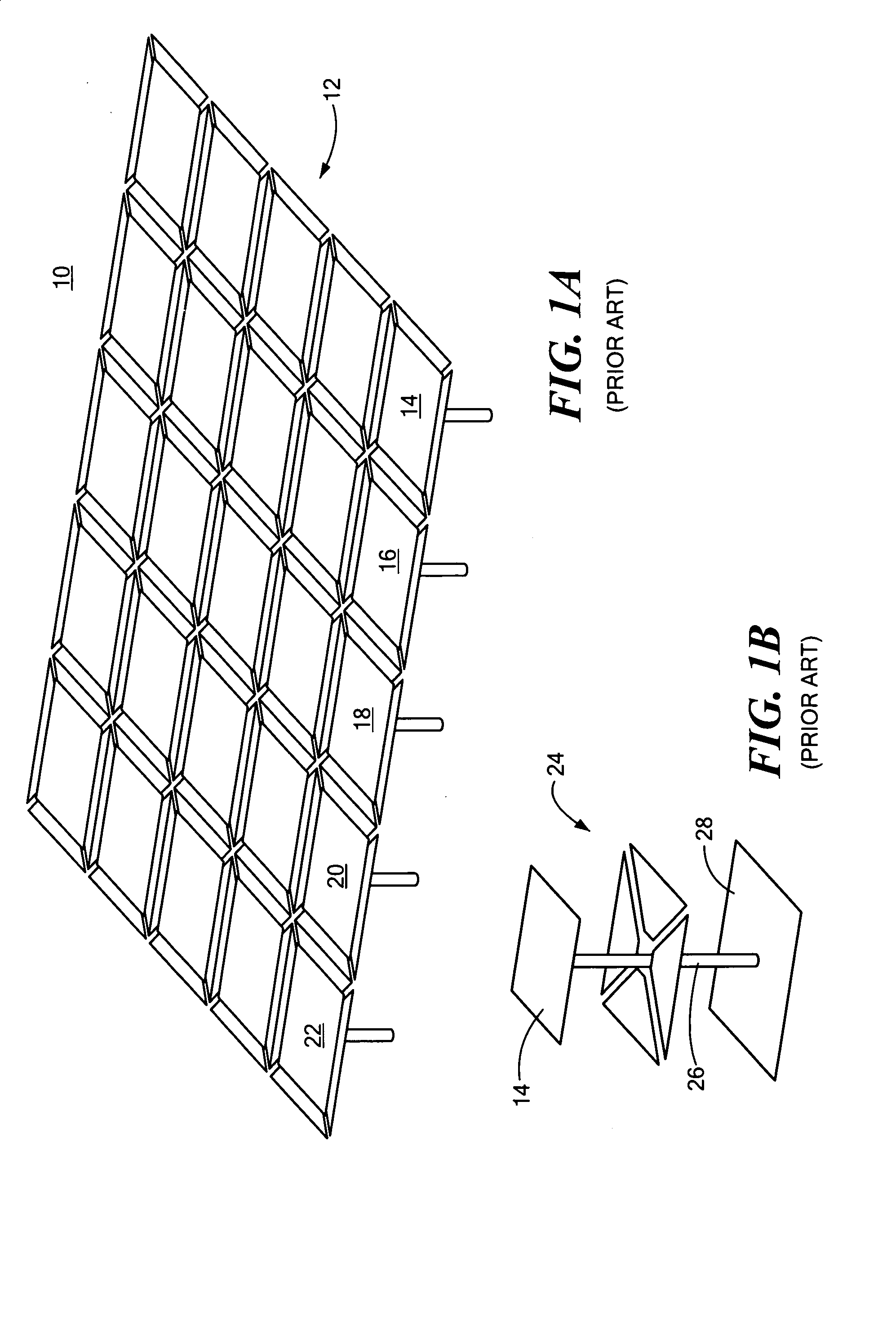
[0048]One conventional metamaterial 10, FIG. 1A, includes periodic array 12 of capacitive-inductive networks comprised o...


PUM


Abstract

An electromagnetic composite metamaterial including an electromagnetic medium and a plurality of spaced electromechanical resonators disposed in or on the electromagnetic medium configured to control electromagnetic wave propagation properties in the electromagnetic composite metamaterial.

Description

RELATED APPLICATIONS[0001]This application claims benefit of and priority to Provisional Application, U.S. Provisional Patent Application No. 60 / 818,093, filed Jun. 30, 2006 incorporated by reference herein.FIELD OF THE INVENTION[0002]This invention relates generally to metamaterials and more particularly to an electromagnetic composite metamaterial for controlling electromagnetic wave propagation properties in the metamaterial.BACKGROUND OF THE INVENTION[0003]Metamaterials are artificial composites that achieve material performance beyond the limitation of uniform materials and exhibit properties not found in naturally-formed substances. Such artificially structured materials are typically constructed by patterning or arranging a material or materials to expand the range of electromagnetic properties of the material.[0004]When an electromagnetic wave enters a material, such as a metamaterial, the electric and magnetic fields of the wave interact with electrons and other charges of ...

Claims


Application Information

Patent Timeline
Patent Type & Authority Applications(United States)
IPC IPC(8): H03H9/00
CPCH03H9/0095H03H9/02393H03H9/171H03H9/2405H03H9/2436H03H9/2457H03H2009/02519H03H9/462H03H9/60H03H2009/02496H03H2009/02503H03H2009/02511H03H9/2473
Inventor DUWEL, AMY E.VARSANIK, JONATHAN S.
Owner CHARLES STARK DRAPER LABORATORY
Why Eureka
Try Eureka