RFID reader and circuit and method for echo cancellation thereof

a technology of rfid reader and circuit, which is applied in the direction of electrical signalling details, mechanical actuation of burglar alarms, instruments, etc., can solve the problems of reducing sensitivity and spuriousness, reducing the sensitivity of echo carriers, and requiring a large amount of time. , to achieve the effect of simple design, improved sensitivity and convenient implementation

Inactive Publication Date: 2008-06-12
IND TECH RES INST
View PDF3 Cites 15 Cited by
  • Summary
  • Abstract
  • Description
  • Claims
  • Application Information

AI Technical Summary

Benefits of technology

[0009]The present invention provides an echo cancellation circuit for an RFID reader. This RFID reader is improved by the echo cancellation circuit and features better sensitivity, broader SFDR, and a simple design easy to be implemented. The performance of echo carrier suppression of the echo cancellation circuit is optimal.

Problems solved by technology

The leakage carrier signal is very undesirable because the difference of power level between the leakage carrier signal and the desired signal from the tag can be as large as 110 dB.
Ideally, the circulator 205 should have a signal isolation of 110 dB from the port P1 to the port P3, but such a requirement is impractical because no such circulator exists.
As a result, the echo problem greatly reduces the sensitivity and the spurious-free dynamic range (SFDR) of the reader 101.

Method used


Image

  • RFID reader and circuit and method for echo cancellation thereof
  • RFID reader and circuit and method for echo cancellation thereof
  • RFID reader and circuit and method for echo cancellation thereof

Examples


Embodiment Construction

[0028]Reference will now be made in detail to the present preferred embodiments of the invention, examples of which are illustrated in the accompanying drawings. Wherever possible, the same reference numbers are used in the drawings and the description to refer to the same or like parts.

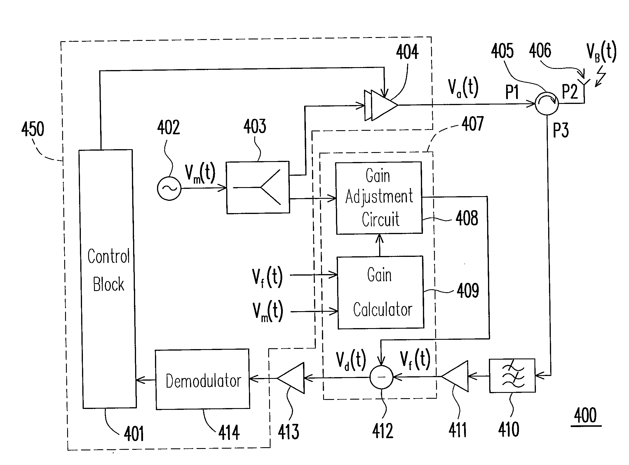
[0029]FIG. 4 is a schematic diagram showing the circuit of an RFID reader 400 including an echo cancellation circuit 407 according to an embodiment of the present invention. The RFID reader 400 includes a backend module 450, a circulator 405, an antenna 406, a band-pass filter (BPF) 410, two low-noise amplifiers (LNAs) 411 and 413, and the echo cancellation circuit 407. The backend module 450 includes a control block 401, an RF oscillator 402, a power splitter 403, a PA 404, and a demodulator 414. Among the components of the RFID reader 400, the control block 401, the RF oscillator 402, the power splitter 403, the circulator 405, the antenna 406, and the demodulator 414 are analogous to their counter...


PUM


Abstract

An echo cancellation circuit for an RFID reader and the method thereof are provided. The echo cancellation circuit includes a gain calculator, a gain adjustment circuit, and a subtraction circuit. The gain calculator provides a complex gain value according to a carrier signal and a received signal through an adaptive algorithm. The gain adjustment circuit is coupled to the gain calculator. The gain adjustment circuit multiplies the carrier signal by the complex gain value, and outputs the result of the multiplication. The subtraction circuit is coupled to the gain adjustment circuit. The subtraction circuit subtracts the output of the gain adjustment circuit from the received signal, and then provides the result of the subtraction as the output signal of the echo cancellation circuit.

Description

CROSS-REFERENCE TO RELATED APPLICATION[0001]This application claims the priority benefit of U.S. application Ser. No. 60 / 869,559, filed Dec. 12, 2006. All disclosure of the U.S. application is incorporated herein by reference.BACKGROUND OF THE INVENTION[0002]1. Field of the Invention[0003]The present invention relates to a radio frequency identification (RFID) reader. More particularly, the present invention relates to a circuit and a method for echo cancellation of an RFID reader.[0004]2. Description of the Related Art[0005]FIG. 1 is a schematic diagram showing a conventional RFID reader 101 and several RFID tags, for example three RFID tags 102-104. The reader 101 emits ultra high frequency (UHF) electromagnetic waves to enable the tags 102-104 so that the tags 102-104 can backscatter data to the reader 101. FIG. 2 is a schematic diagram showing the circuit of a conventional RFID reader 101. The RFID reader 101 includes an RF oscillator 201, a power splitter 202, a power amplifier...

Claims


Application Information

Patent Timeline
Patent Type & Authority Applications(United States)
IPC IPC(8): G08B1/08
CPCG06K7/10346G06K7/0008
Inventor LIN, CHIH-HUNGLI, CHIN-FUYU, CHIA-JENCHEN, JIUNN-TSAIR
Owner IND TECH RES INST
Why Eureka
Try Eureka