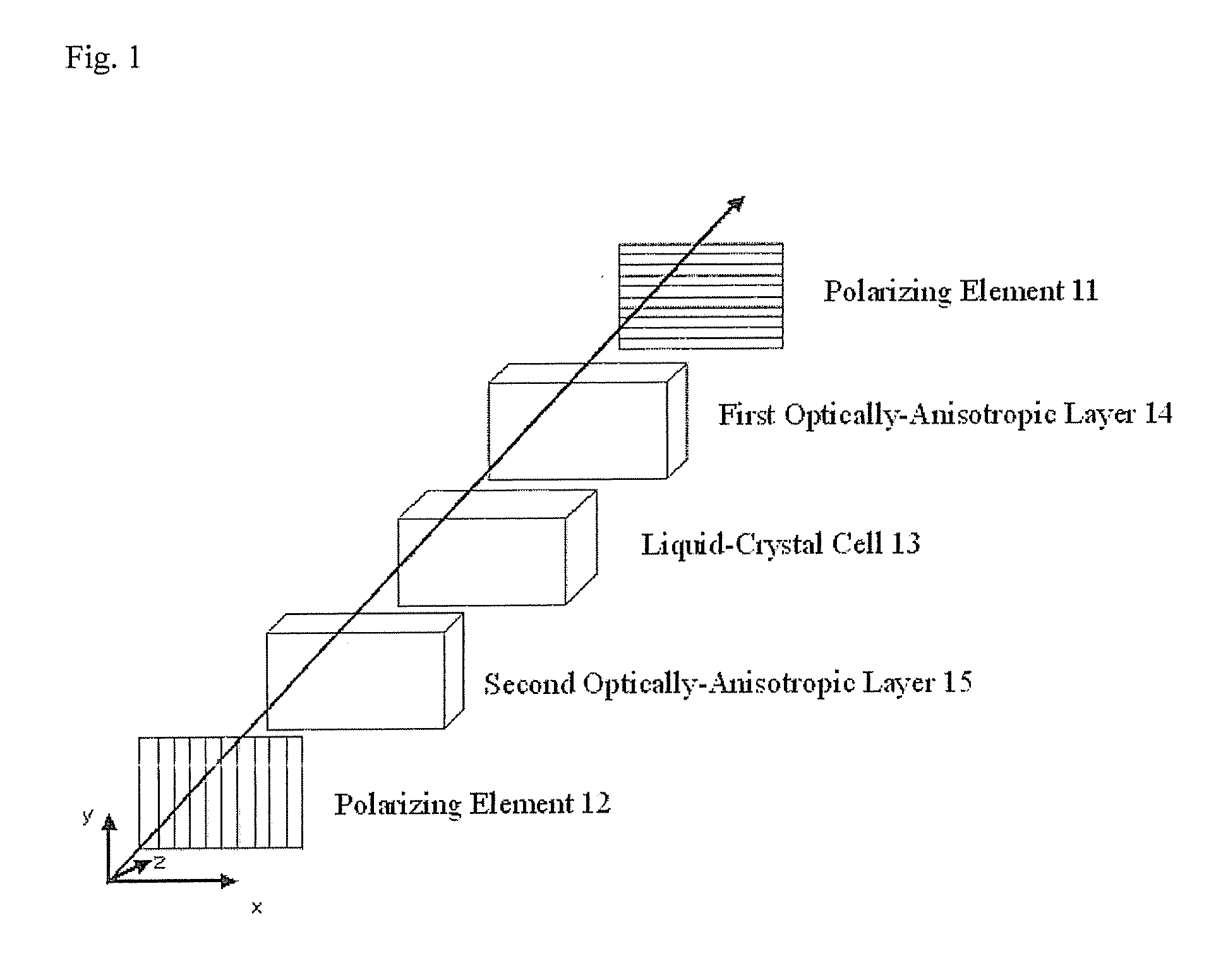
[0059]One embodiment of the liquid
crystal display device of the invention is shown in FIG. 1. The invention may be effective for liquid
crystal display devices of any liquid crystal
modes, not depending on the driving
system of the devices. As one example of the invention, FIG. 1 shows one embodiment of the constitution of a VA-mode liquid
crystal display device. The liquid
crystal display device of FIG. 1 comprises a
liquid crystal cell 13, and a pair of polarizing element 11 and polarizing element 12 disposed on both sides of the
liquid crystal cell 13 as sandwiched therebetween. Between the polarizing element 11 and the liquid
crystal cell 13, the device has an optically anisotropic layer 14 that satisfies the above relations (1) and (2); and between the polarizing element 12 and the liquid
crystal cell 13, it has an optically anisotropic layer 15 having at least one
optical axis. The polarizing elements 11 and 12 are disposed that their transmission axes are parallel to each other. Preferably, the second optically anisotropic layer 15 is so disposed that the in-plane slow axis thereof is perpendicular to the absorption axis of the polarizing element 12.
[0060]Any of the polarizing elements 11 and 12 may be on the backlight side or the display panel side of the device. The first optically anisotropic layer 14 and the second optically anisotropic layer 15 may be disposed as protective films for the polarizing elements 11 and 12, as kept in contact with the surface of each element. Between the polarizing element 11 and the first optically anisotropic layer 14, and between the polarizing element 12 and the second optically anisotropic layer 15, other protective films for them may be separately disposed; and the protective films are preferably isotropic films having a retardation of nearly zero (0).
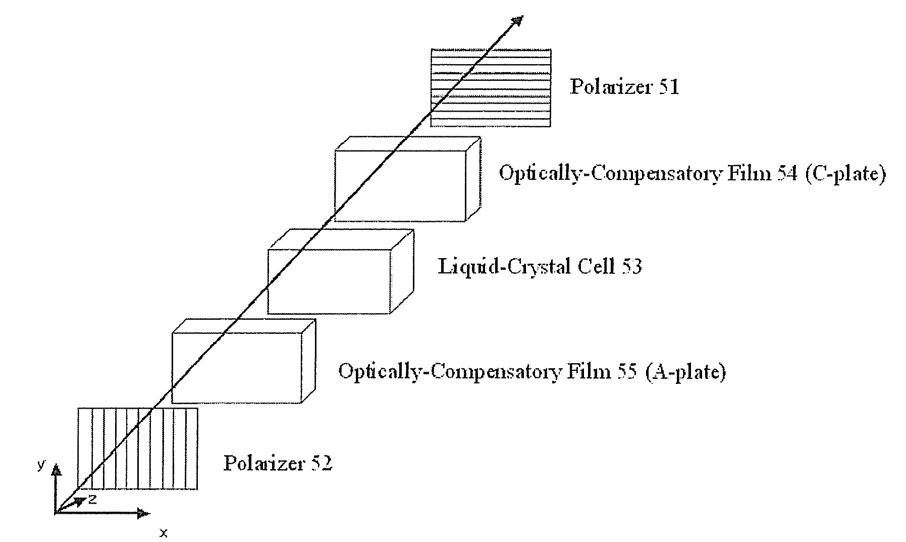
[0061]The effect of the invention is described with reference to the drawings. For comparison, FIG. 7 is given as a
schematic view showing the constitution of an ordinary VA-mode liquid crystal
display device. The VA-mode liquid crystal display device generally comprises a liquid
crystal cell 53 that has a liquid crystal layer in which the liquid crystal is vertically aligned relative to the substrate face in no
voltage application thereto, or that is, in the black state, and polarizers 51 and 52 that are so disposed as to sandwich the liquid crystal
cell 53 therebetween and that their transmission axes (shown by stripes in FIG. 7) are perpendicular to each other. In FIG. 7, light comes into the device from the side of the
polarizer 52. When light comes into the device in the normal direction, or that is, in the z-axis direction in no
voltage application to the device, then the light having passed through the
polarizer 52 further passes through the liquid crystal 53
cell while keeping its
linear polarization state, and then completely blocked by the
polarizer 51. As a result, the device displays a high-contrast image.
[0062]However, the condition differs in oblique light application as in FIG. 8. When light comes in the device not in the z-axis direction but in an oblique direction, or that is, when the incident light to the device is in the oblique direction relative to the polarization direction of the polarizers 51 and 52 (so-called off-axis), then the incident light is influenced by the oblique-direction retardation while passing through the vertically-aligned liquid crystal layer of the liquid crystal
cell 53, whereby its polarization state changes. Further, the apparent transmission axes of the polarizer 51 and the polarizer 52 shift from the perpendicularly-crossing disposition. Because of these two factors, the incident light in the oblique direction in the off-axis condition could not be completely blocked by the polarizer 51, and as a result, there may occur light leakage in the black state, thereby causing contrast reduction.
[0063]A polar angle and an
azimuth angle are defined herein. The polar angle is an angle as inclined in the normal direction of a film face, or that is, from the z-axis in FIG. 7 and FIG. 8, and, for example, the normal direction of the film face is a direction at a polar angle of 0 degree. The
azimuth angle indicates a direction as rotated in the counterclockwise direction based on the
positive direction of the x-axis, and for example, the
positive direction of the x-axis is a direction at an
azimuth angle of 0 degree. The
positive direction of the y-axis is a direction of an azimuth angle of 90 degrees. The above-mentioned oblique direction in off-axis condition mainly indicates a case where the polar angle is not 0 degree and the azimuth angle is 45 degrees, 135 degrees, 225 degrees or 315 degrees.
[0064]Heretofore, it is proposed to solve the problem of contrast reduction in the oblique direction in a VA-mode liquid crystal display device, by the use of a biaxial plate and a C-plate (for example, Japanese Laid-Open Patent Publication No. 2003-344856). Heretofore, various stretched
polymer films are used in optically-compensatory films; but in general, most stretched
polymer films satisfy a relation of Re(450)≧Re(550)≧Re(650) and Rth(450)≧Rth(550)≧Rth(650), or that is, they have larger Re or Rth values at shorter visible wavelengths (hereinafter this characteristic is occasionally referred to as “regular
wavelength dispersion characteristic of Re or Rth” respectively; and the reversed characteristic, or in other words the characteristic having larger Re and Rth values at longer visible wavelengths, is occasionally referred to as “reversed
wavelength dispersion characteristic of Re or Rth” respectively).

