Light emitting diode heat dissipating module and display apparatus applied thereto

a heat dissipating module and diode technology, applied in lighting and heating apparatus, semiconductor devices for light sources, lighting support devices, etc., can solve the problems of large volume, direct impact on product reliability and lifespan, and large volume, so as to improve the conventional heat pipe, reduce the effect of length limitation and increase design flexibility

Inactive Publication Date: 2008-06-12
DELTA ELECTRONICS INC
View PDF3 Cites 21 Cited by
  • Summary
  • Abstract
  • Description
  • Claims
  • Application Information

AI Technical Summary

Benefits of technology

[0008]A detailed description is given in the following embodiments with reference to the accompanying drawings. The invention provides a light emitting diode heat dissipating module and a display apparatus utilizing the same. The invention improves the conventional heat pipe by eliminating length limitation of conventional heat

Problems solved by technology

Products with multiple functions, due to the integration of many electronic elements in one device, increases heat generation, and thus heat-dissipation efficiency directly affects product reliability and lifespan.
If heat dissipation is provided by natural convection only, large numbers of fins are necessary, which causes big volume, heavy weight and high cost for the entire LED heat dissipating module 10.
Thus, the heat dissipating efficiency near the upper end of the fins is poor.
Even though an additional fan is added to provide airflo

Method used


Image

  • Light emitting diode heat dissipating module and display apparatus applied thereto
  • Light emitting diode heat dissipating module and display apparatus applied thereto
  • Light emitting diode heat dissipating module and display apparatus applied thereto

Examples


Embodiment Construction

[0020]The following description is of the best-contemplated mode of carrying out the invention. This description is made for the purpose of illustrating the general principles of the invention and should not be taken in a limiting sense. The scope of the invention is best determined by reference to the appended claims.

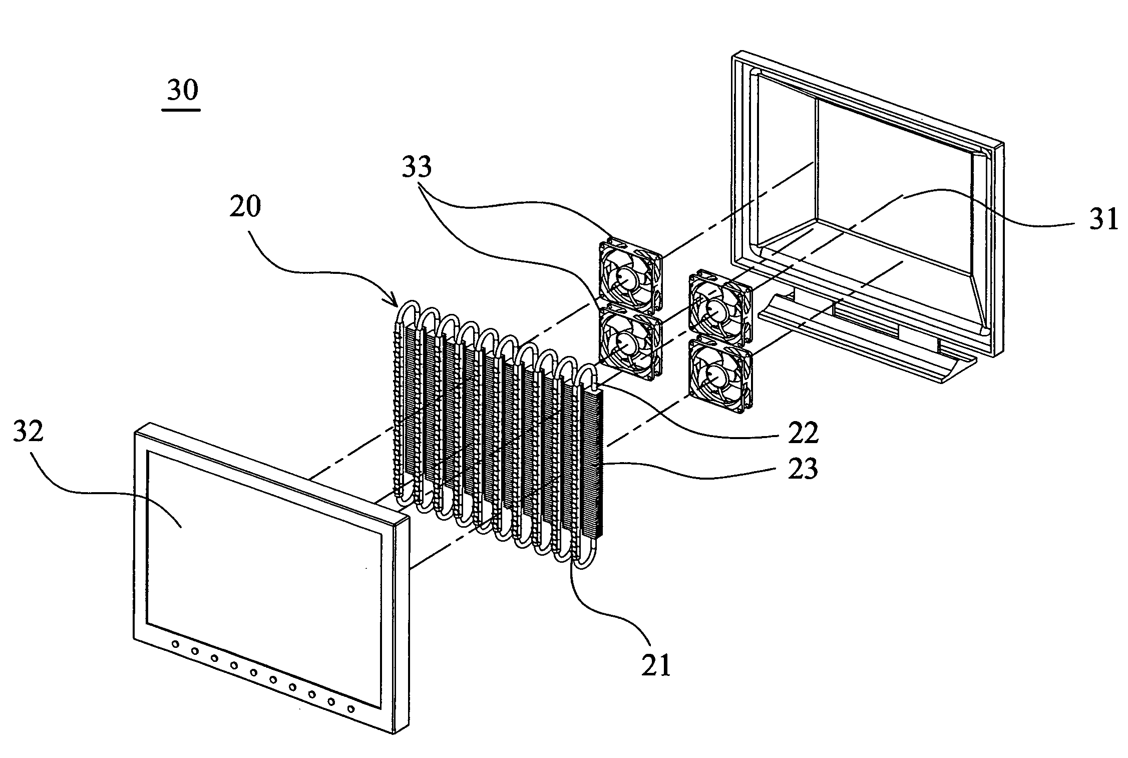
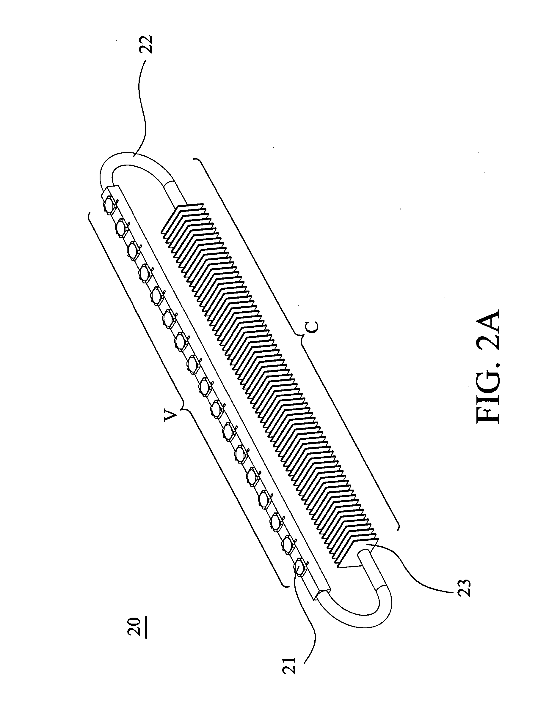
[0021]FIG. 2A is a schematic view of an embodiment of a light emitting diode heat dissipating module of the present invention. FIG. 2B is a cross sectional view of FIG. 2A. Please refer both to FIGS. 2A and 2B, the light emitting diode heat dissipating module 20 includes a plurality of light emitting diodes(LEDs) 21, a pulsating heat pipe 22 and a plurality of fins 23. The LEDs 21 are respectively installed on the pulsating heat pipe 22, and the fins 23 are connected to the pulsating heat pipe 22. The pulsating heat pipe 22 is made of a material with high heat conductivity, such as aluminum, copper, titanium, molybdenum, silver, stainless steel, carbon steel, or other ...


PUM


Abstract

A display apparatus, such as a rear projection television, includes a housing, a display panel and a plurality of LED heat dissipating modules disposed in the housing. The display panel is connected to the housing, and each of the LED heat dissipating modules includes a pulsating heat pipe, a plurality of fins, and a plurality of LEDs for providing light to the display panel. The LEDs are disposed on the pulsating heat pipe and located at the vaporizing section, and the fins are connected to the pulsating heat pipe and all located at the condensing section for increasing the heat dissipating area.

Description

[0001]This Non-provisional application claims priority under U.S.C. §119(a) on Patent Application No(s). 095145985, filed in Taiwan, Republic of China on Dec. 8, 2006, the entire contents of which are hereby incorporated by reference.BACKGROUND OF THE INVENTION[0002]1. Field of the Invention[0003]The invention relates to a heat dissipating module and a display apparatus utilizing the same, and more particularly to a heat dissipating module and a display apparatus utilizing the same applied to a light emitting diode.[0004]2. Description of the Related Art[0005]Because science and technology gradually progresses, electronic products must provide more functions. The variety and functionality of personal computers continually increases. Portable computers, PDAs, cell phones, a handheld computer are the topics of a great deal of research. Products with multiple functions, due to the integration of many electronic elements in one device, increases heat generation, and thus heat-dissipatio...

Claims


Application Information

Patent Timeline
IPC IPC(8): F21V29/00F21V21/00
CPCF21K9/00F28D15/043H04N9/3144H04N9/315F21V29/763H05K7/2099F21V29/006F21V29/677H05K7/20972F28D15/0266F21Y2115/10
Inventor CHENG, CHIN-MINGLEE, YI-SHENG
Owner DELTA ELECTRONICS INC
Why Eureka
Try Eureka