
Wireless audio speaker system

a speaker system and wireless technology, applied in the field of speaker systems, can solve the problems of affecting the and limiting the orientation and position of the speaker, so as to achieve the effect of convenient portability of the speaker

Inactive Publication Date: 2008-06-12
BROOKSTONE PURCHASING
View PDF6 Cites 37 Cited by
  • Summary
  • Abstract
  • Description
  • Claims
  • Application Information

AI Technical Summary

Benefits of technology

[0007]In view of the problems described previously, embodiments of the present invention provide a system that enables power and / or audio signals to be transmitted to a speaker without connecting external wires or cables to the speaker. In particular, embodiments of the present invention provide a system for connecting a speaker to a power source without connecting a power cord to the speaker. Moreover, embodiments of the present invention provide a system for connecting a speaker to a power source while allowing the speaker to be rotated to face in any direction. Advantageously, embodiments of the present invention also make speakers easily portable.

Problems solved by technology

External wire connections are difficult to manage and organize, particularly when there are many devices and many wire connections, as is the case with even simple entertainment systems.
In addition, external speaker wire connections may limit the orientation and position of a speaker with respect to the position of a listener.
A speaker generally directs sound in a specific direction, but the wires leading from the speaker may prevent the speaker from being easily oriented, or turned, to direct sound toward a desired location.
Furthermore, external wire connections limit the portability of speakers.
In view of the growth in the popularity of portable electronic media devices, limited portability is often considered to be a significant disadvantage.

Method used


Image

  • Wireless audio speaker system
  • Wireless audio speaker system
  • Wireless audio speaker system

Examples


Embodiment Construction

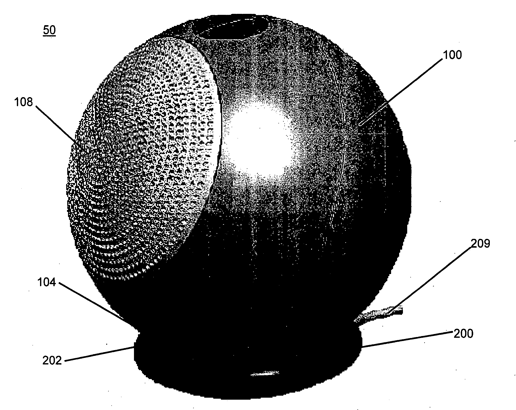
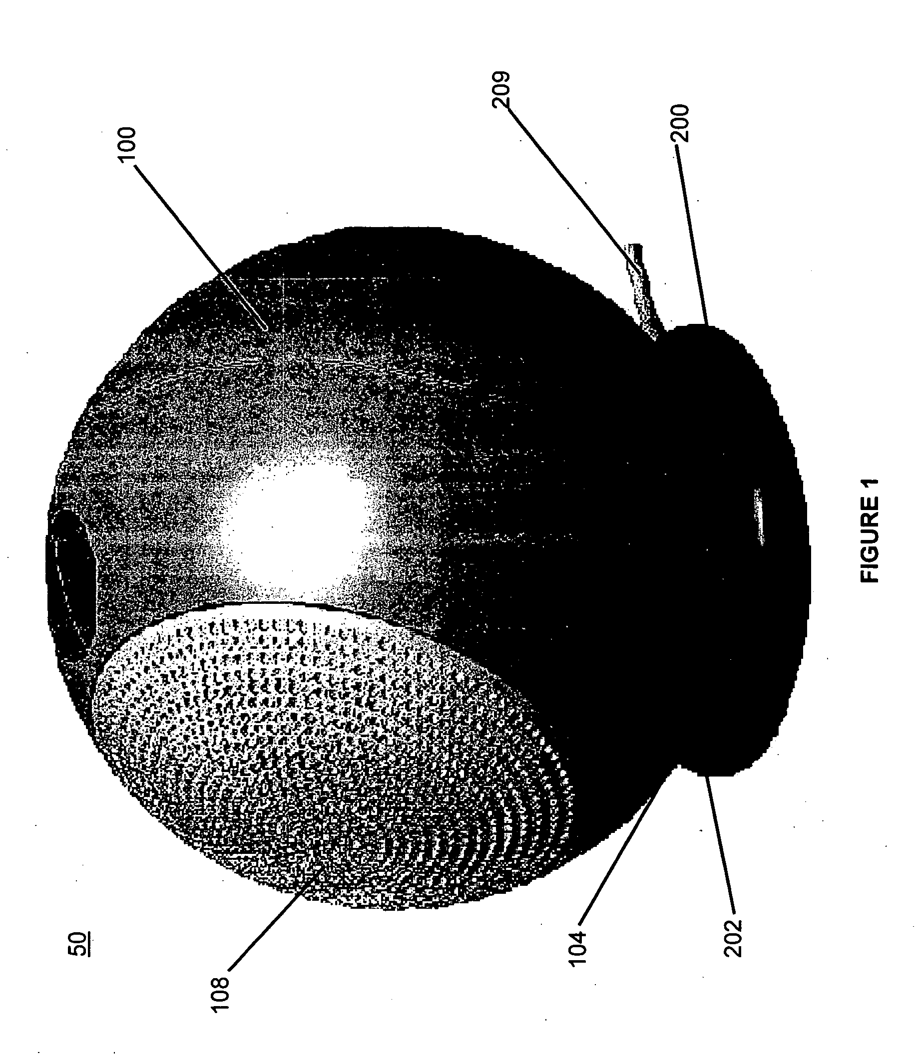
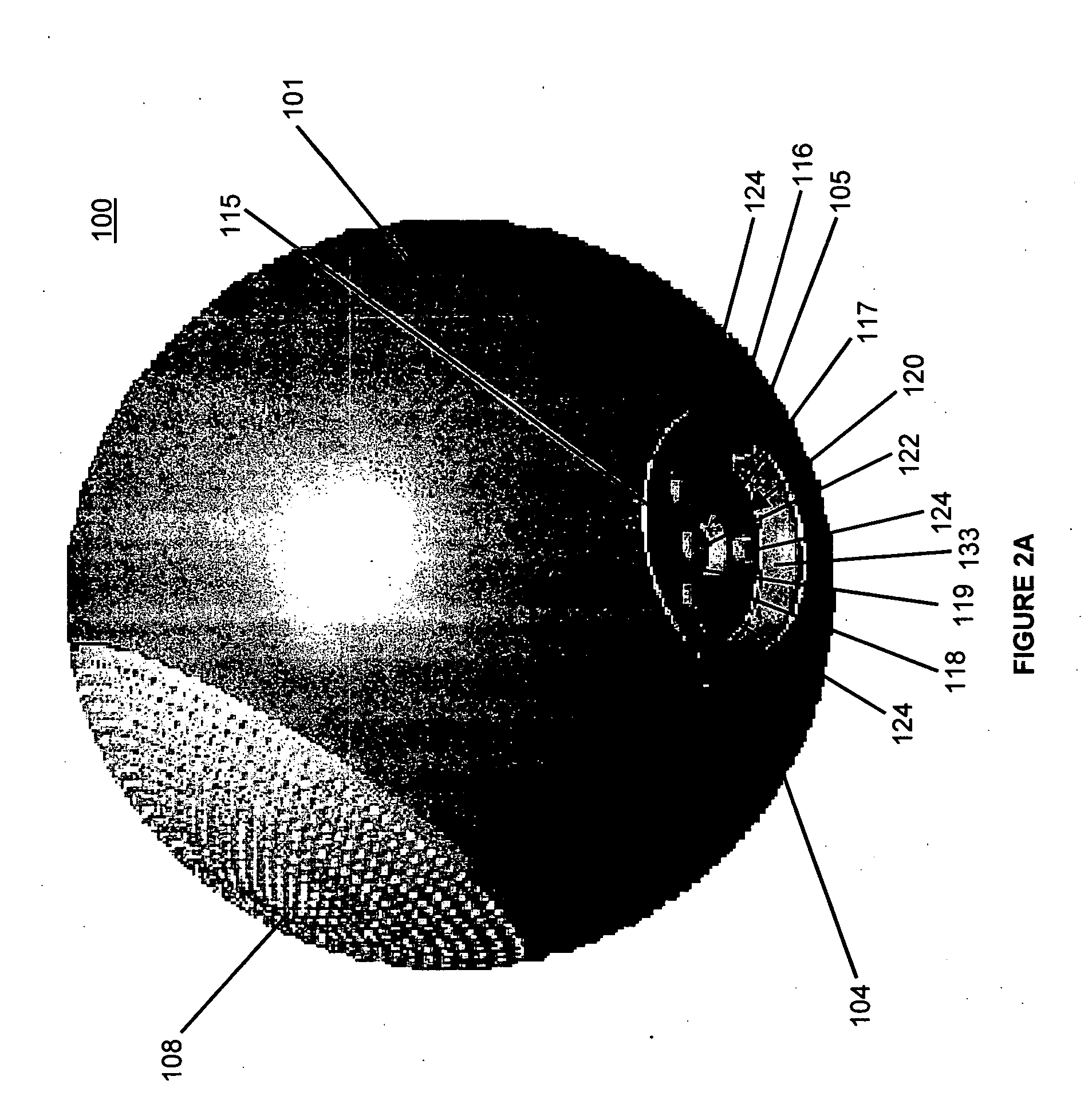
[0019]Referring to FIG. 1, an exemplary embodiment of the present invention is generally illustrated as a speaker system 50 which includes a speaker 100 and an electrical power delivery base 200. In particular, the speaker 100 may be a rechargeable wireless speaker, which is recharged by electricity delivered from the electrical power delivery base 200. The speaker 100 receives wireless signal transmissions from an audio signal producing device. An audio signal producing device produces an audio signal that can be converted into sound, but the audio signal producing device requires an output device, such as a speaker, to convert the signal into sound. Such audio producing devices may include, but are not limited to, radio receivers, television systems, DVD players, CD players, digital or magnetic tape players, video game consoles, personal computers with media players, and portable personal audio players such as MP3 players. The speaker 100 converts the wireless signals it receives ...


PUM


Abstract

A speaker system employs a first device and a second device where one of the first device and the second device is a speaker. The first device has a supporting surface, from which a positioning element protrudes and forms a distal end. The positioning element tapers from the supporting surface to a smaller dimension at the distal end. The second device has a cavity receiving the positioning element. In one embodiment, the first device has a first electrical contact positioned adjacent to the positioning element and the second device has a second electrical contact engaging the first electrical contact. In another embodiment, the first and second device are rotationally repositionable relative to one another, and an electrical connection is created between the first device and the second device when the cavity receives the positioning element at more than one relative rotational position between the first device and the second device.

Description

BACKGROUND OF THE INVENTION[0001]1. Field of the Invention[0002]This invention relates generally to a speaker system, and more particularly, to a system for delivering power to a wireless speaker system.[0003]2. Description of Related Art[0004]A wide range of electronic devices is available to present media content. Such devices include radio receivers, television systems, DVD players, CD players, digital or magnetic tape players, video game consoles, personal computers with media players, and portable personal audio players such as MP3 players.[0005]These electronic media devices generally work by processing data or signals they receive from various media. For example, a radio receiver receives and processes broadcast signals transmitted from a broadcast tower or satellite; a CD player reads and processes the digital data on a CD; or an MP3 player reads and processes digital data stored on a memory device. An output device, such as a television monitor or a set of speakers, is requ...

Claims


Application Information

Patent Timeline
IPC IPC(8): H04B5/00
CPCH04R1/06H04R1/026
Inventor MILLS, STEPHEN B.LI, VIAN W.Y
Owner BROOKSTONE PURCHASING
Learn More