
Condenser microphone having flexure hinge diaphragm and method of manufacturing the same

Inactive Publication Date: 2008-06-12
ELECTRONICS & TELECOMM RES INST
View PDF10 Cites 34 Cited by
  • Summary
  • Abstract
  • Description
  • Claims
  • Application Information

AI Technical Summary

Benefits of technology

[0017]Etching the sacrificial layer, the passivation layer, the conductive layer, the upper silicon layer, the first insulating layer and the lower silicon layer may include: etching the passivation layer, the conductive layer, the upper silicon layer, the first insulating layer and the lower silicon layer by the DRIE process; and etching the sacrificial layer by a wet etching process. To prevent deformation of the diaphragm during etching of the sacrificial layer, the method may further include: coating a photoresist layer on the diaphragm before etching the sacrificial layer; and removing the photoresist layer after etching the sacrificial layer.

Problems solved by technology

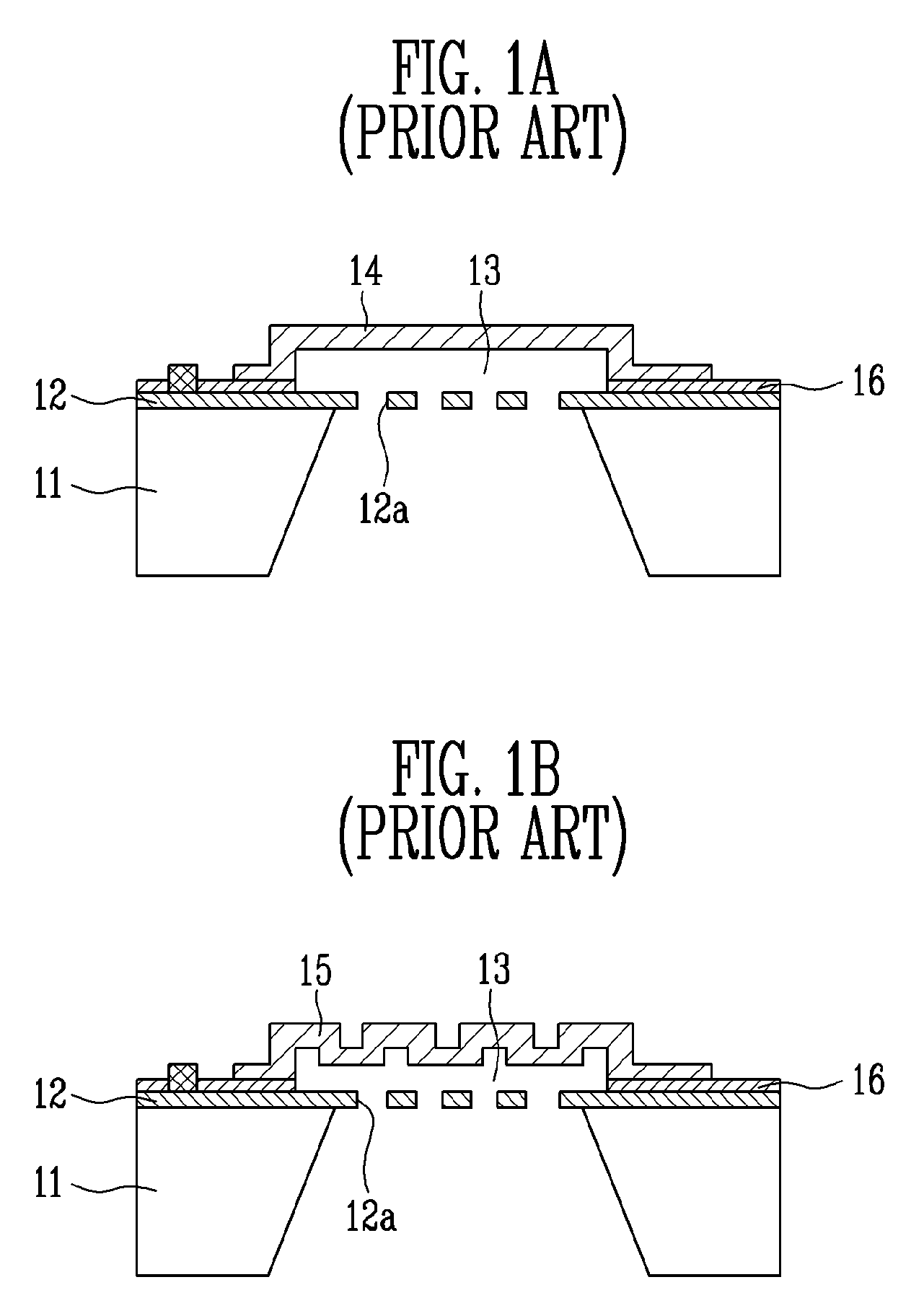
However, sufficient sound pressure has to be input to vibrate the diaphragms of these condenser microphones.
Moreover, the conventional condenser microphones having the conventional structure described above have poor performance in a low frequency range when scaled-down to 1 mm or less using a semiconductor MEMS process.

Method used


Image

  • Condenser microphone having flexure hinge diaphragm and method of manufacturing the same
  • Condenser microphone having flexure hinge diaphragm and method of manufacturing the same
  • Condenser microphone having flexure hinge diaphragm and method of manufacturing the same

Examples


Embodiment Construction

[0025]Hereinafter, the present invention will be described in detail with reference to drawings illustrating exemplary embodiments of the present invention.

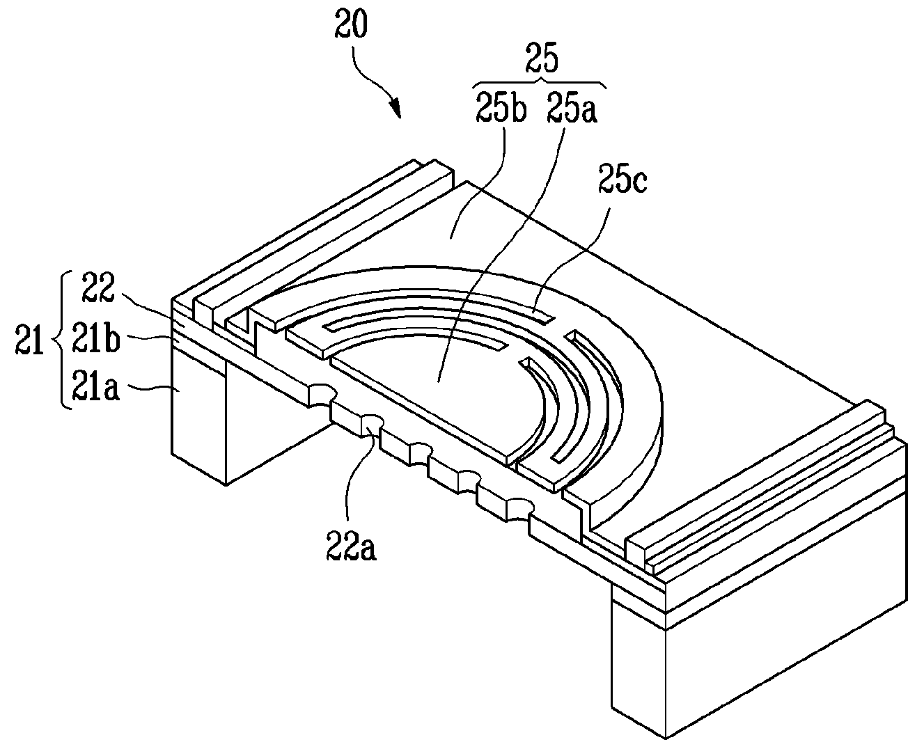
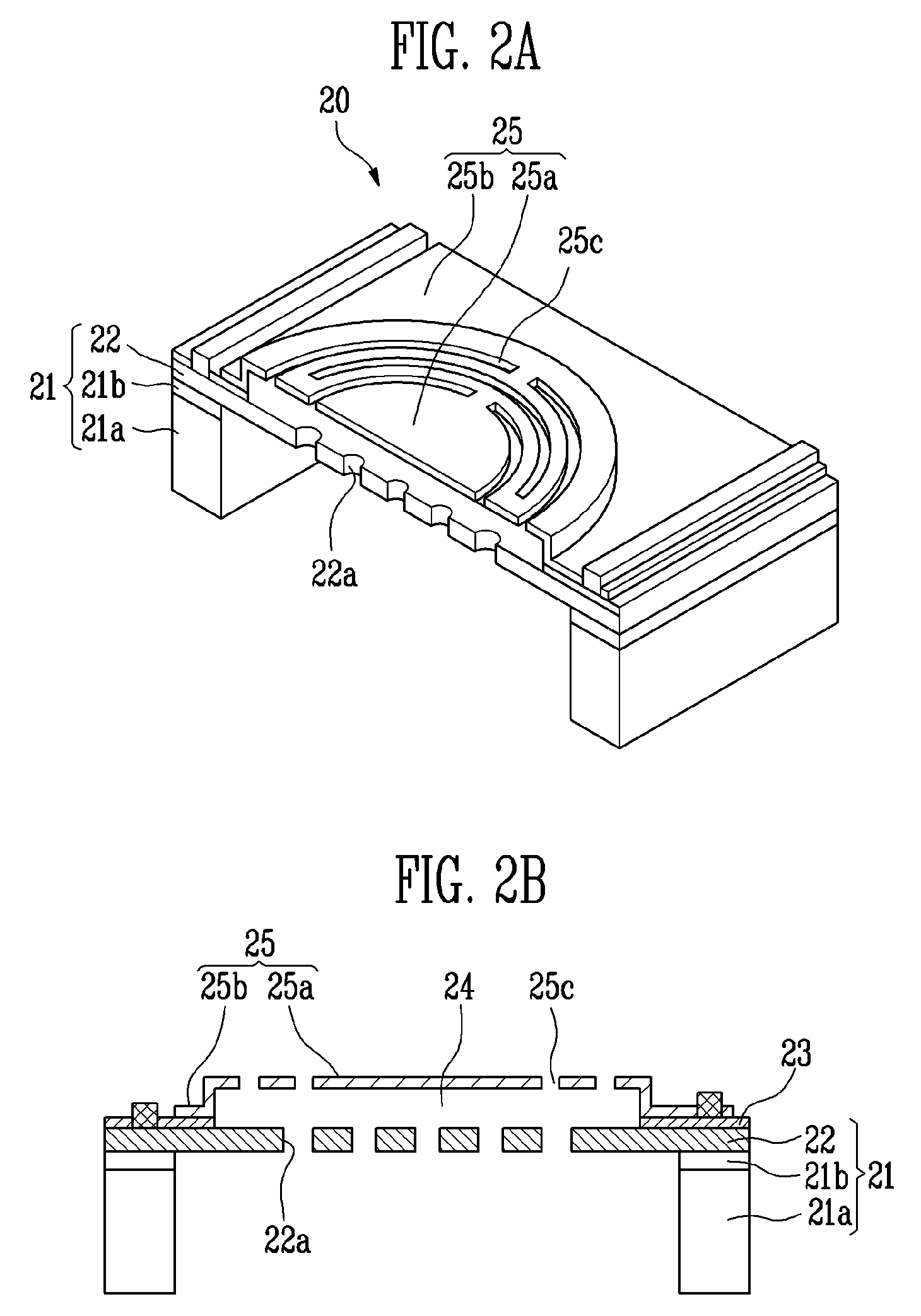
[0026]FIG. 2A is a partial perspective view of a structure of a condenser microphone having a flexure hinge diaphragm according to the present invention, and FIG. 2B is a cross-sectional view of the structure of the condenser microphone having the flexure hinge diaphragm according to the present invention. For convenience of description, sectional lines for some elements such as a sound hole and an air hole will be omitted.

[0027]Referring to FIGS. 2A and 2B, a condenser microphone 20 according to the present invention includes a silicon on insulator (SOI) wafer 21 including a lower silicon layer 21a, a first insulating layer 21b and an upper silicon layer 22 used as a back plate (hereinafter, referred to as “a back plate 22”), a second insulating layer 23 formed along an edge of the back plate 22, and a diaphragm 25 formed over t...


PUM

PropertyMeasurementUnit
Thicknessaaaaaaaaaa
Metallic bondaaaaaaaaaa
Deformation enthalpyaaaaaaaaaa

Abstract

A micromini condenser microphone having a flexure hinge-shaped upper diaphragm and a back plate, and a method of manufacturing the same are provided.The method includes the steps of: forming a lower silicon layer and a first insulating layer; forming an upper silicon layer to be used as a back plate on the first insulating layer; forming a plurality of sound holes by patterning the upper silicon layer; forming a second insulating layer on the upper silicon layer; forming a conductive layer on the upper silicon layer having the sound holes, and forming a passivation layer on the conductive layer; forming a sacrificial layer on the passivation layer; depositing a diaphragm on the sacrificial layer, and forming a plurality of air holes passing through the diaphragm; forming electrode pads on the passivation layer and a region of the diaphragm; and etching the sacrificial layer, the passivation layer, the conductive layer, the upper silicon layer, the first insulating layer and the lower silicon layer to form an air gap between the diaphragm and the upper silicon layer.Consequently, due to the flexible diaphragm, a manufacturing process using semiconductor MEMS technology may improve the sensitivity of the condenser microphone and reduce the size of the condenser microphone, thereby enabling integration into a portable terminal.

Description

CROSS-REFERENCE TO RELATED APPLICATION[0001]This application claims priority to and the benefit of Korean Patent Application Nos. 2006-122736, filed Dec. 6, 2006, and 2007-54259, filed Jun. 4, 2007, the disclosures of which are incorporated herein by reference in their entirety.BACKGROUND[0002]1. Field of the Invention[0003]The present invention relates to a condenser microphone and a method of manufacturing the same, and more particularly, to a micromini condenser microphone having a flexure hinge diaphragm and a method of manufacturing the same.[0004]This work was supported by the IT R&D program of Ministry of Information and Communication / Institute for Information Technology Advancement [2006-S-006-01, Components / Module technology for Ubiquitous Terminals.][0005]2. Discussion of Related Art[0006]Generally, a condenser microphone uses a principle in which a change in capacitance caused by vibration of a diaphragm due to external vibration sound pressure is output into an electrica...

Claims


Application Information

Patent Timeline
IPC IPC(8): H04R25/00H01L21/64
CPCH04R31/00Y10T29/41H04R31/003H04R2499/11H04R19/005
Inventor KIM, HYE JINLEE, SUNG Q.PARK, KANG HOKIM, JONG DAE
Owner ELECTRONICS & TELECOMM RES INST
Learn More