Exhaust Apparatus For Use in Administering Positive Pressure Therapy Through the Nose or Mouth

a positive pressure therapy and exhaust pipe technology, applied in the field of exhaust pipe valves, can solve the problems of complex intubation and treatment failure, and achieve the effects of reducing source flow requirements, reducing treatment failure, and superior co2 removal

Inactive Publication Date: 2008-06-19
HALLETT MICHAEL DAVID +1
View PDF8 Cites 69 Cited by
  • Summary
  • Abstract
  • Description
  • Claims
  • Application Information

AI Technical Summary

Benefits of technology

[0009]We describe the use of a flow directing apparatus for incorporation into the patient mask or adjacent to it and for use with electronically or electronically controlled fan blowers or positive displacement ventilators to provide nasal or oro-nasally administered CPAP or bi level therapies. These devices will provide a pressured source of breathable gas (usually room air or oxygen enriched room air) Typical source pressures are in the range 0 to 50 cm H20, the exact pressures or combinations being determined by individual patient requirements. Applicable conditions can include but not limited to treatment of sleep apnea, sleep hyperventilation syndromes, lung disease. The device is able to direct exhaust gases to atmosphere during expiration, while directing air to patients airway during inhalation. Hence the device is unique compared to the constant or variable flow exhaust area devices as described in the prior art and does not depend at all on a continuous bias flow. The operation of the device can be most easily described as an automatically adjusting PEEP (positive end expiratory pressure) valve, where the PEEP pressure is governed by the pressure delivered by an electrically operated and hence variable pressure source as opposed to a manually adjusted mechanical design. This device has important implications for use in positive pressure therapies particularly those that are administered via a face mask and hence includes the upper airway, as opposed users who are acutely intubated. Specifically, such as system may be used where the pressure is constant (CPAP) or varying i.e. pressures are varied during the respiratory cycle being higher to actively inflate long and reduced to deflate the lung to varying degrees and needs of the treatment. For example, during active assisted inhalation, pressurized air from the source is actively directed exclusively to the patients airway in the absence of unintended mask leaks. Conversely when the pressure source senses or preempts an expiratory emptying, the system is able to direct air exclusively to the atmosphere. In this context only tidal air is expired to atmosphere in the absence of a mask leak or perfectly sealed system. This is contrast to the prior art wherein bi level devices, such as described in U.S. Pat. No. 5,148,802 where the mask system described is of a fixed vent size type. This means that during exhalation expired air will be partially transmitted down the gas delivery tube from the pressure source and only partially out the exhalation vent. It will require fixed period of time to adequately wash out the CO2 from the tube prior to the next inhalation cycle. This is a significant disadvantage of the prior art and the need to optimize the vent size to ensure rapid CO2 washout prior to the next inspiration. Clinically, it has been observed in nasal ventilation bi-level systems at rapid respiratory rates, as much as 50% of the expired tidal volume is rebreathed. Clearly in acute situations where patients may be very hypercapnic and in respiratory distress, rebreathing such a high proportion of their tidal volume may lead to treatment failure and need for more complex intubation. Despite this shortcoming, in view of the added management issues with intubation nasal ventilation will be the preferred line of treatment. Furthermore the invention disclosed here will require an alternative arrangement for triggering specifically from expiration to inspiration. Hence the prior art does not anticipate the invention when used in a bi level mode and it provides the advantages which include superior CO2 removal and potential for less rebreathing, reduced source flow requirements, reduced need for humidification or when external humidification is required improved efficiency, improved noise characteristics, and absence of biased flow onto sleeping partners.

Problems solved by technology

This is a significant disadvantage of the prior art and the need to optimize the vent size to ensure rapid CO2 washout prior to the next inspiration.
Clearly in acute situations where patients may be very hypercapnic and in respiratory distress, rebreathing such a high proportion of their tidal volume may lead to treatment failure and need for more complex intubation.

Method used


Image

  • Exhaust Apparatus For Use in Administering Positive Pressure Therapy Through the Nose or Mouth
  • Exhaust Apparatus For Use in Administering Positive Pressure Therapy Through the Nose or Mouth
  • Exhaust Apparatus For Use in Administering Positive Pressure Therapy Through the Nose or Mouth

Examples


Embodiment Construction

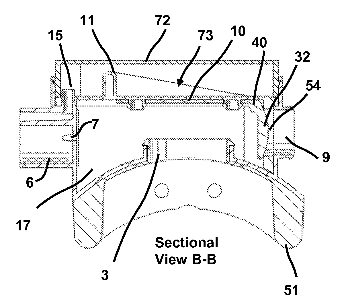
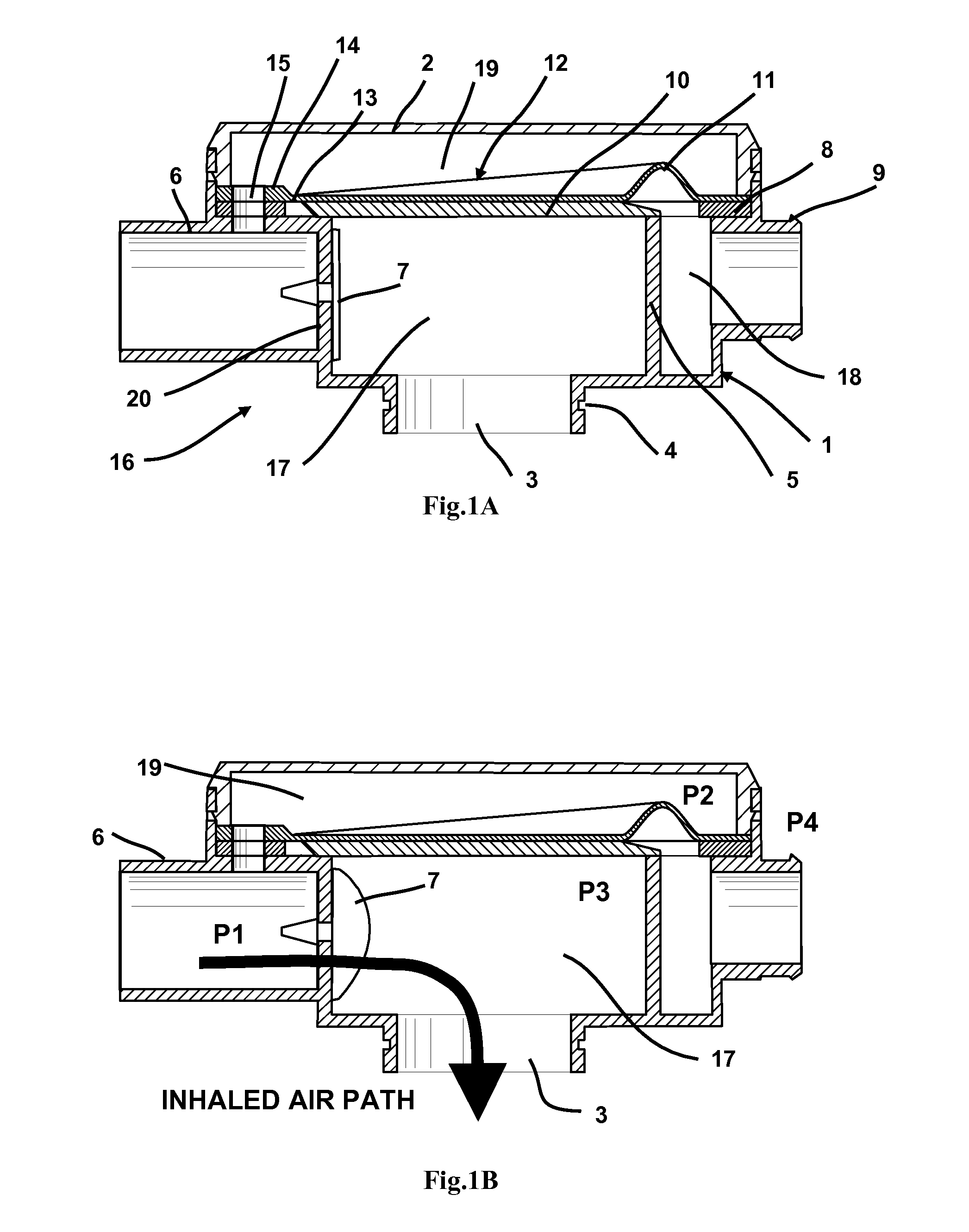
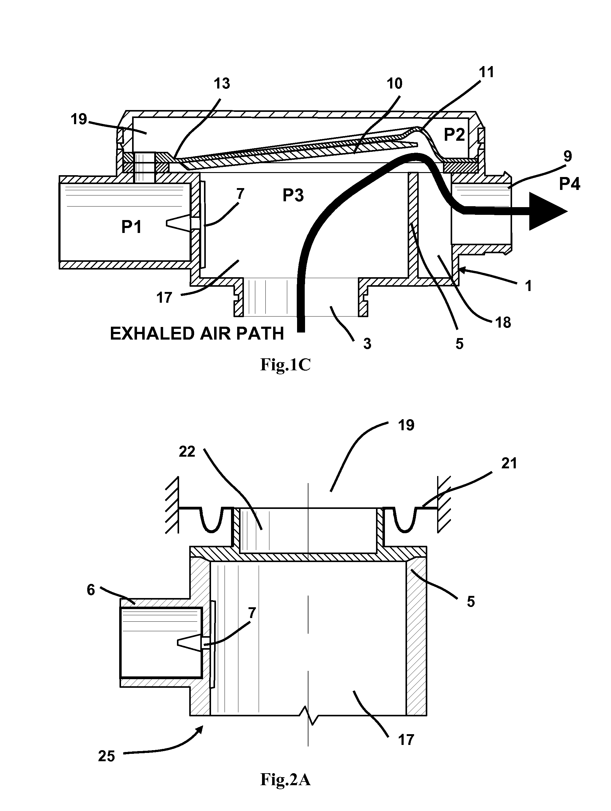
[0021]FIGS. 1A-1D illustrate a first embodiment of the invention. Referring to FIG. 1A, a valve assembly 16 comprises a rigid valve body 1 which includes an inlet passage 6 which is supplied with breathable gas under pressure. Inlet passage 6 terminates at an inner peripheral wall 5 where it intersects primary chamber 17. A non-return valve 7 is applied at the junction between the inlet passage 6 and the primary chamber 17. Non-return valve is attached to the rigid valve body 1. In the example shown, non-return valve 7 comprises a resilient flap weakly biased to the closed position and structured to deflect into two halves about a central line defined by mounting bar 20 which symmetrically bridges the junction between inlet passage 6 and primary chamber 17. Means of attachment comprising a barb-through-hole arrangement as widely used for this type of valve. It will be appreciated that the non-return valve 7 may take alternate forms such as a resilient flap weakly biased to the close...


PUM


Abstract

We describe the use of a flow directing apparatus for incorporation into a patient mask or adjacent to it and for use with a source of pressurized breathable gas such as electronically or electronically controlled fan blower or positive displacement ventilator to provide nasal or oro-nasally administered continuous positive airway pressure or bi level therapies. Such therapies are commonly used to treat sleep disordered breathing including sleep apnea and other syndromes, as well as ventilatory insufficiency. The valve apparatus includes means to direct expired air to atmosphere and inspired air from a pressure source to a user's airway. In this way advantage is provided compared to alternative means as described in the prior art which vent a user's expired gas to atmosphere through a fixed open vent.

Description

CROSS REFERENCE TO RELATED APPLICATIONS[0001]This patent is a full specification based on Australian provisional patent applications with numbers 2006904948, 2006904950STATEMENT REGARDING FEDERALLY SPONSORED RESEARCH OR DEVELOPMENT[0002]Not ApplicableREFERENCE TO SEQUENCE LISTING, A TABLE, OR A COMPUTER PROGRAM LISTING COMPACT DISK APPENDIX[0003]Not ApplicableBACKGROUND TO THE INVENTION[0004]The prior art in relation to exhaust valves used with nasally administered continuous positive airway pressure (CPAP) or active ventilation techniques, where a range of pressures are often used, a lower pressure for a substantial period of exhalation compared to inspiration, are related commercially to a fixed leak to atmosphere; that is a vent of fixed cross sectional area and the flow varies in proportion to the applied pressure (square root of pressure) within the circuit comprising the flow and pressure source, a connecting tube, nasal mouth mask and the users airway and lung network. The us...

Claims


Application Information

Patent Timeline
Patent Type & Authority Applications(United States)
IPC IPC(8): A62B9/02
CPCA61M16/06A61M16/0683A61M16/208A61M2205/3306A61M16/209A61M2205/3365A61M2205/3375A61M16/0633A61M2205/3317A61M16/0638A61M16/206
Inventor HALLETT, MICHAEL DAVIDGUNARATNAM, MICHAEL KASSIPILLAI
Owner HALLETT MICHAEL DAVID
Why Eureka
Try Eureka