Environmental condition control for an energy-conversion unit

a technology of environment condition control and energy conversion unit, which is applied in the direction of light radiation electric generator, semiconductor device, electrical apparatus, etc., can solve the problems of reducing affecting the efficiency of light-to-electrical conversion unit, so as to reduce the chance of failure and less stress

Inactive Publication Date: 2008-06-19
SOLFOCUS
View PDF9 Cites 17 Cited by
  • Summary
  • Abstract
  • Description
  • Claims
  • Application Information

AI Technical Summary

Benefits of technology

[0005]Embodiments of the present invention control the environment of a volume containing an energy conversion system. The energy conversion system is thus protected from moisture and contaminants from an outside environment and also from differentials between pressures in the volume containing the energy conversion system and pressures in an outside environment. By controlling these pressure differentials, less stress is placed on seals and other components of the energy conversion system, reducing their chance of failure.

Problems solved by technology

When moisture forms on an element that focuses the light onto the receiving area in a solar concentrator system, the light is no longer accurately focused thereon.
A few millimeter deviation can quickly reduce the efficiency of the light-to-electrical conversion unit from 500 suns to a fraction of that amount.
Moisture within the volume results in other problems, such as the diffusion into semiconductor devices and the corrosion of electrical leads and other metal parts.

Method used


Image

  • Environmental condition control for an energy-conversion unit
  • Environmental condition control for an energy-conversion unit
  • Environmental condition control for an energy-conversion unit

Examples


Embodiment Construction

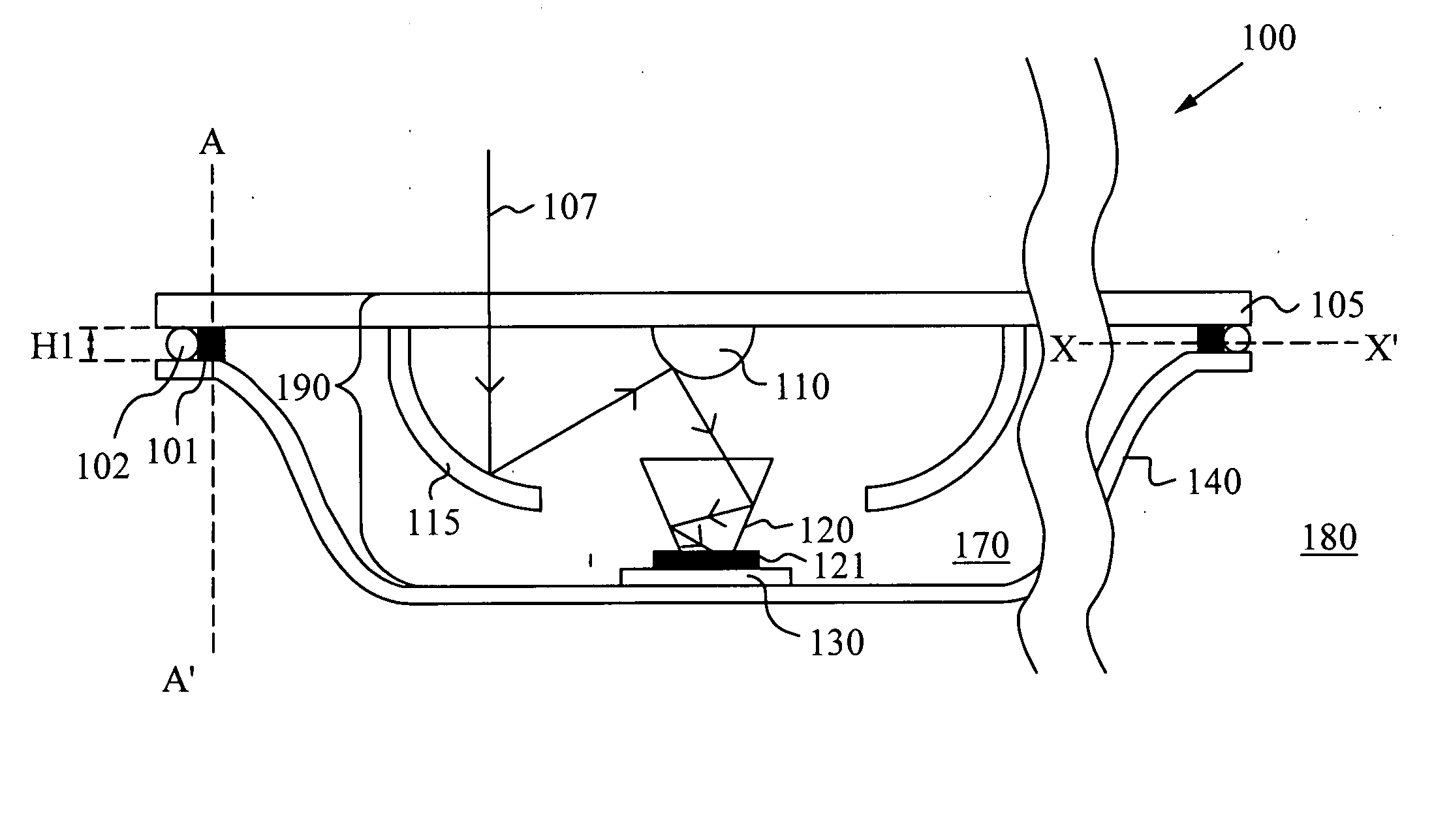
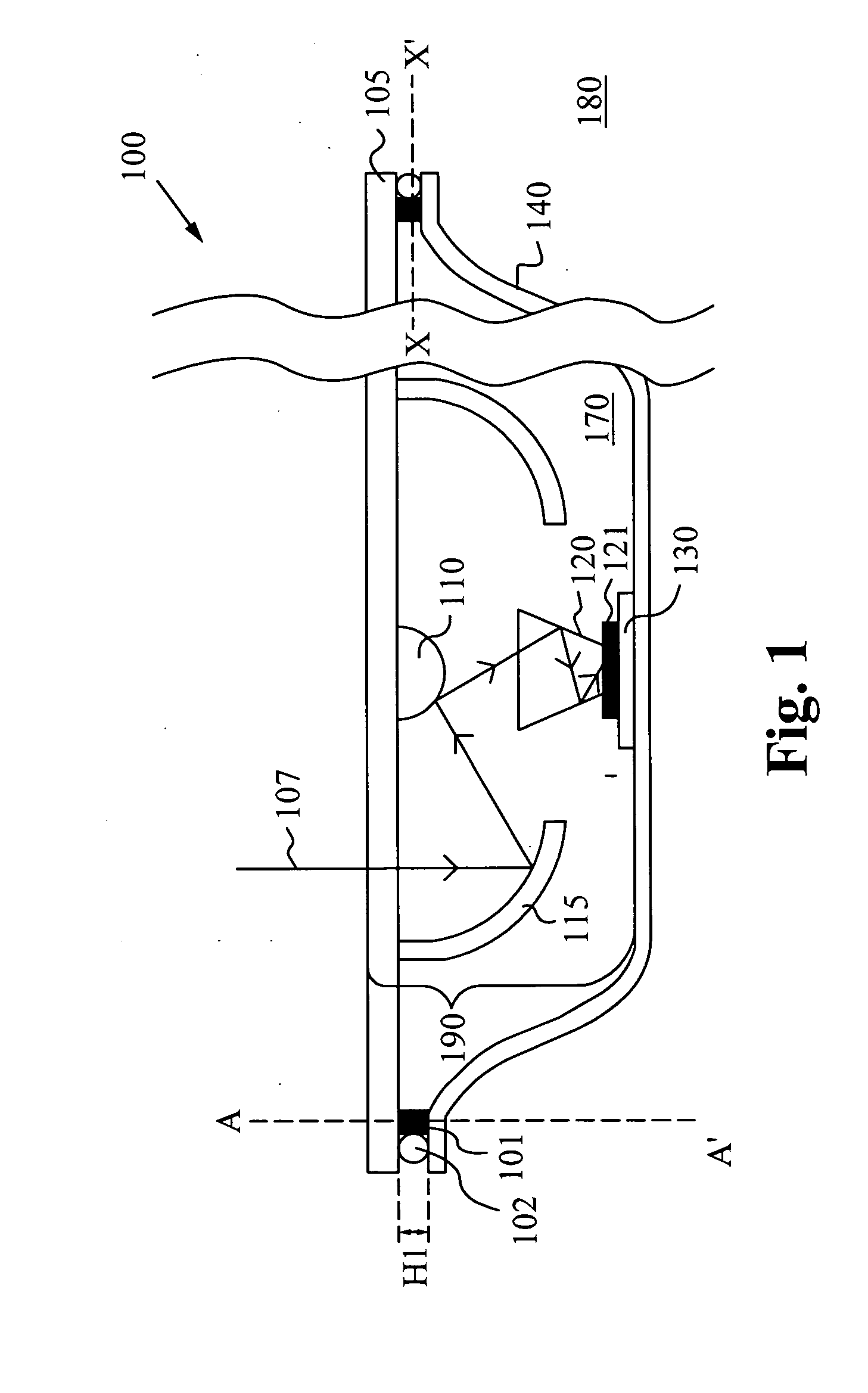
[0037]Energy-conversion units, such as concentrator photovoltaic devices (both fresnel lens and mirror optic based structures), are generally enclosed within chambers that provide structure and protection from an outside environment. The outside environment contains moisture, dust and pollutants. Pressure fluctuations within these units can be caused by temperature changes, barometric pressure changes, and the like. Embodiments of the present invention maintain an inside volume of a chamber separate from outside moisture, from outside contaminants, from pressure fluctuations, or any combination of these. The pressure fluctuation of the outside environment is very minimal compared to the pressure fluctuation within a totally sealed chamber due to temperature changes within the chamber. Thus, embodiments of the invention are designed to keep the chamber pressure equal to (or within a small band of) the pressure of the outside environment.

[0038]FIG. 1 is a side cross-sectional view of ...


PUM


Abstract

Embodiments of the present invention control an atmosphere of a volume surrounding an energy conversion unit, such as a concentrator photovoltaic device. Differences between pressures within the volume and pressures outside the volume are controlled to reduce stress on seals and to prevent contaminants and moisture from flowing into the volume. A chamber for housing an energy conversion unit in accordance with one embodiment includes a housing and a controller. The housing defines a first unit volume for containing the energy conversion unit. The controller is coupled to the first unit volume and automatically controls an environment in the first unit volume. In one embodiment, the controller provides a flow path from a second unit volume outside the housing to a bladder within the first unit volume. In other embodiments, the controller provides gas that maintains a slight positive differential between a pressure of the first unit volume and a pressure of the second unit volume, thereby ensuring that gas and thus contaminants do not flow from the second unit volume into the first unit volume. In still other embodiments, the flow path from the second unit volume into the first unit volume includes a labyrintine tube.

Description

FIELD OF THE INVENTION[0001]This invention relates to chambers for housing energy-conversion units. More specifically, this invention relates to chambers that hermetically seal light-to-electrical conversion units.BACKGROUND OF THE INVENTION[0002]As their efficiency increases, energy conversion units are becoming more cost effective and attractive sources of energy. A light-to-electrical conversion unit takes solar energy and converts it into electricity for use in homes and businesses. Some light-to-electrical conversion units have efficiencies of at least 35%, and that number is increasing. By tracking the sun, these units can convert light to electricity during a large portion of the day.[0003]A light-to-electrical conversion unit has components that are sensitive to moisture and, accordingly, is enclosed in a sealed volume that protects it from the outside atmosphere. The unit includes optics that guide incoming light to a receiving area of the light-to-electrical conversion uni...

Claims


Application Information

Patent Timeline
Patent Type & Authority Applications(United States)
IPC IPC(8): H02N6/00
CPCH01L31/048H01L31/0547Y02E10/52
Inventor SPENCER, MARKHORNE, STEPHEN
Owner SOLFOCUS
Why Eureka
Try Eureka