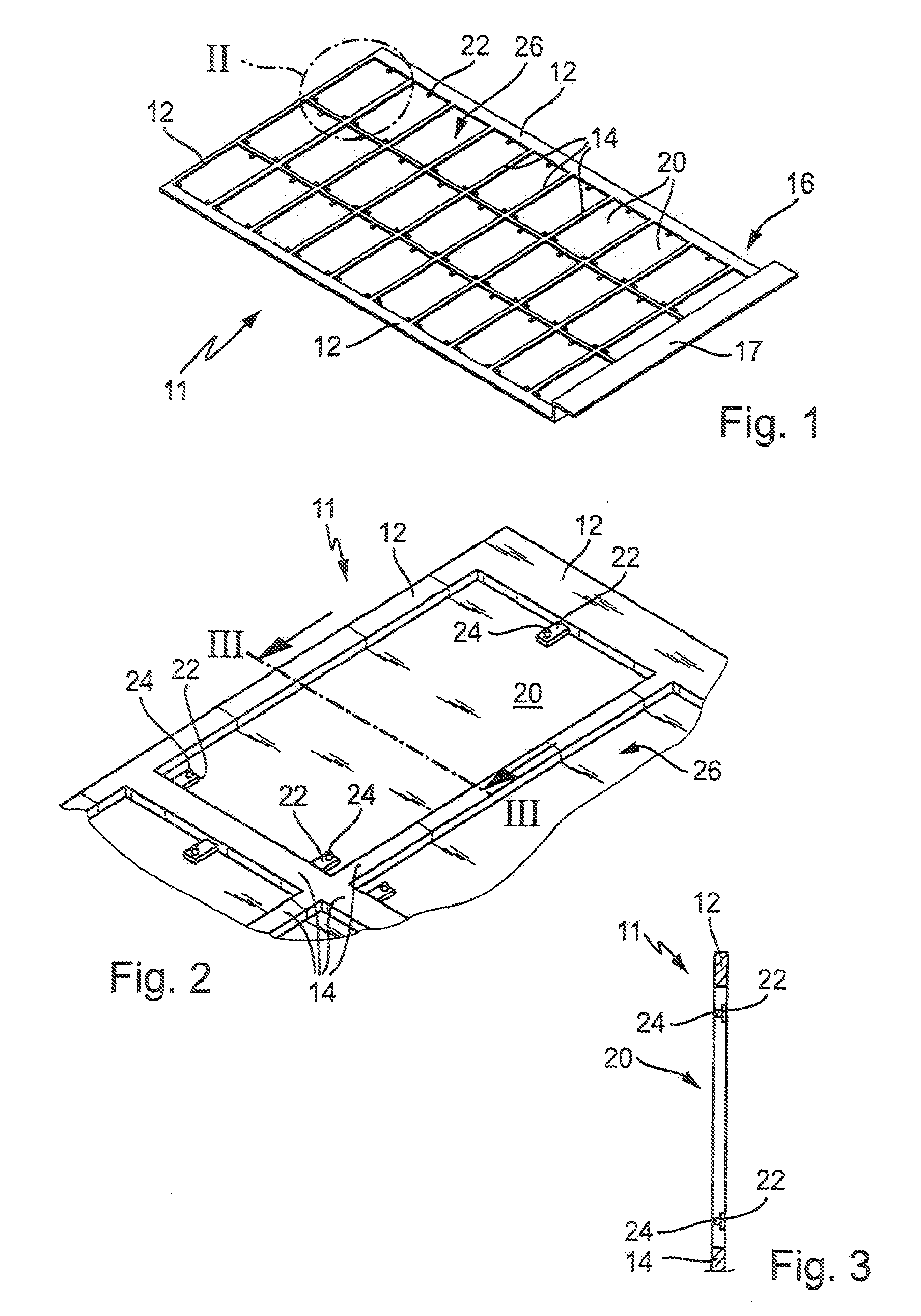
[0005]According to the invention the device has a frame with frame pieces forming reception zones between them and as a result of the frame pieces recesses or cutouts are formed. The frame pieces can run in grid-like manner, particularly with an outer frame and intermediate frame pieces as subdivisions. The frame pieces have supports for the substrates on which the substrates rest. Thus, the mechanical holding of the substrates and / or an electrical contacting takes place on the substrate side engaging on the supports. In this way a reception device or holder for several flat substrates can be created, in which the substrates are placed in the reception zones. For various treatment steps with respect to the substrates, as well as for conveying and in certain circumstances also storage, there is no need to move the individual substrates and instead the complete reception device is moved. The latter can be made more robust than the substrates, so that it is readily possible to use conventional gripping devices or the like. As a result of the supports there can be a precisely defined connection between the reception device and the substrate, which can be matched to
specific substrate characteristics. As a result of the reception device it is possible in the case of a plurality of substrates to not only move one substrate in connection with individual working steps, but instead all the substrates of a reception device can be moved. If electrical contacting with the substrates takes place via the reception device or the supports, in certain cases it is possible to economize additional contacting devices directly on the substrates. This also has the
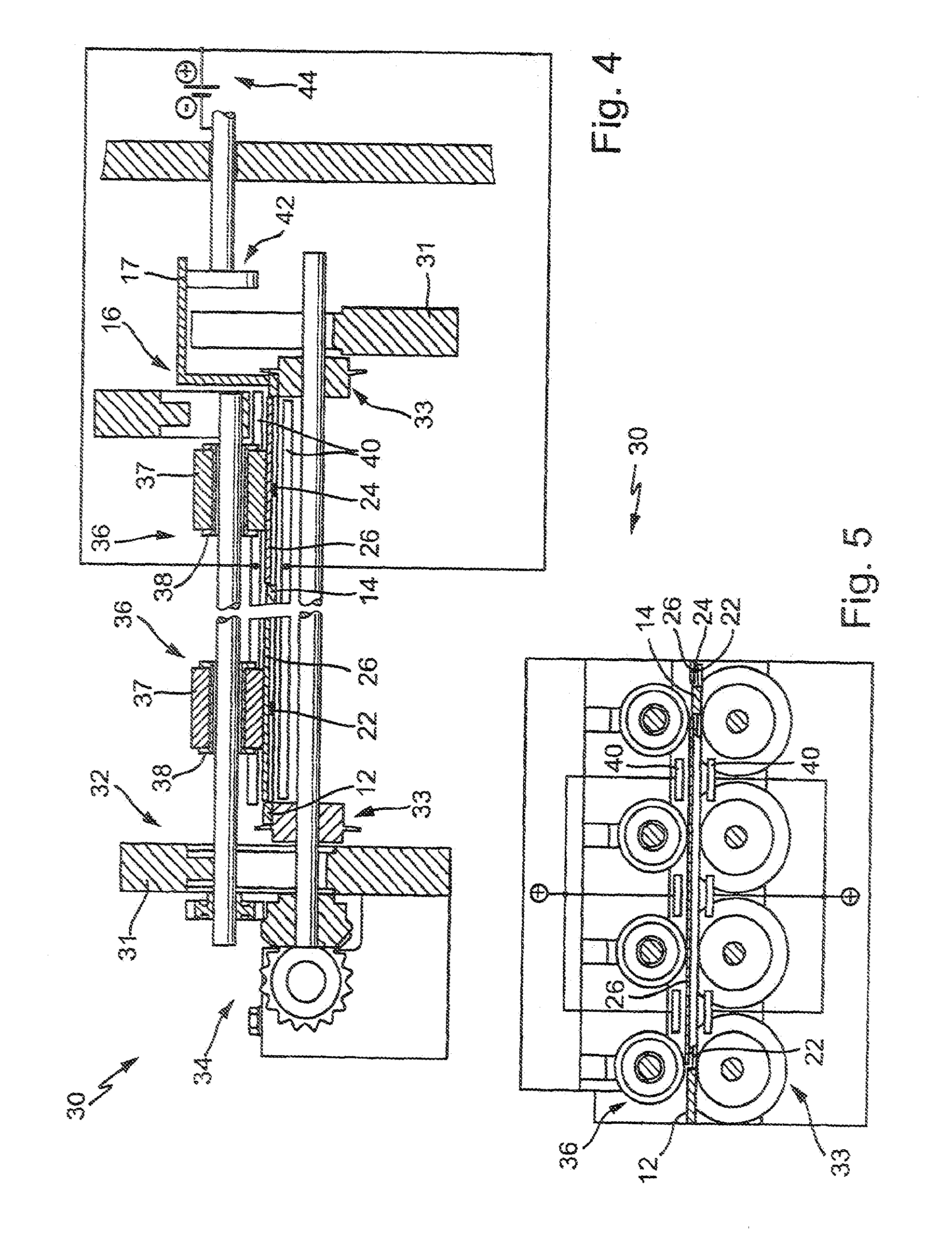
advantage that the mechanical loading of the substrates by contact rollers or other contacting devices can be reduced or avoided. Thus, advantageously the reception device brings about both a mechanical holding or reception of the substrates and also an electrical contacting thereon.
[0006]The supports can for example be constructed as projections, which project or emanate from the frame pieces. The projections can either be relatively narrow, i.e. almost punctiform, in order to bring about a very limited surface coverage on the substrates. This permits a contact with a treatment medium in a galvanizing device in an advantageous, very large-area manner. Alternatively the projections can be wider in order to bring about a type of linear supporting of the substrates with their marginal area on the receptacles or frame pieces. This permits an adequately stable supporting or bearing action, especially with sensitive substrates, because there is a distribution thereof. The projections can also run below the plane of the frame pieces, for example by a downward bend. This makes it possible to have the bearing substrates in roughly one plane with the holder or the frame pieces. It is also possible for the projections to project downwards over the plane formed by the underside of the frame pieces. Advantageously the substrates rest in the reception device or on the projections in such a way that their top side is not below the plane of the top side of the frame pieces and instead preferably projects by a small amount. This makes it possible to ensure that rollers or the like engaging from above in all cases also engage on the top side of the substrates and not mainly on the frame pieces projecting over the substrates.
[0009]In a further development of the invention, it is possible to provide the reception device with an electrically insulating
coating, for example paint or a covering. This avoids any deposition of
coating material on the receptacle during a galvanizing process. If such deposition of
coating material takes place on the aforementioned contacts as exposed surfaces of the reception device, then at certain time intervals said contacts must be cleaned or stripped free, as is known to the expert.
[0010]A part or section of the device can project on an outside, particularly an outer area or from an outside frame piece. This is advantageously bent upwards from the plane of the substantially flat device, particularly with a further sideways bending following onto the same. If said projecting section is for example electrically conductively connected to the frame pieces or
electrical contacts for the engagement of the substrates, then via said section there can be an electrical contacting with the reception device. For this purpose, the section can for example be made from the same material as the remainder of the device, for example it can be rough worked from the aforementioned
metal sheet. It is advantageously possible to construct the entire reception device integrally or in one piece. Said section can also be used for the gripping of the reception device in an area which is remote from the inserted substrates, so as to provide protection for the same.
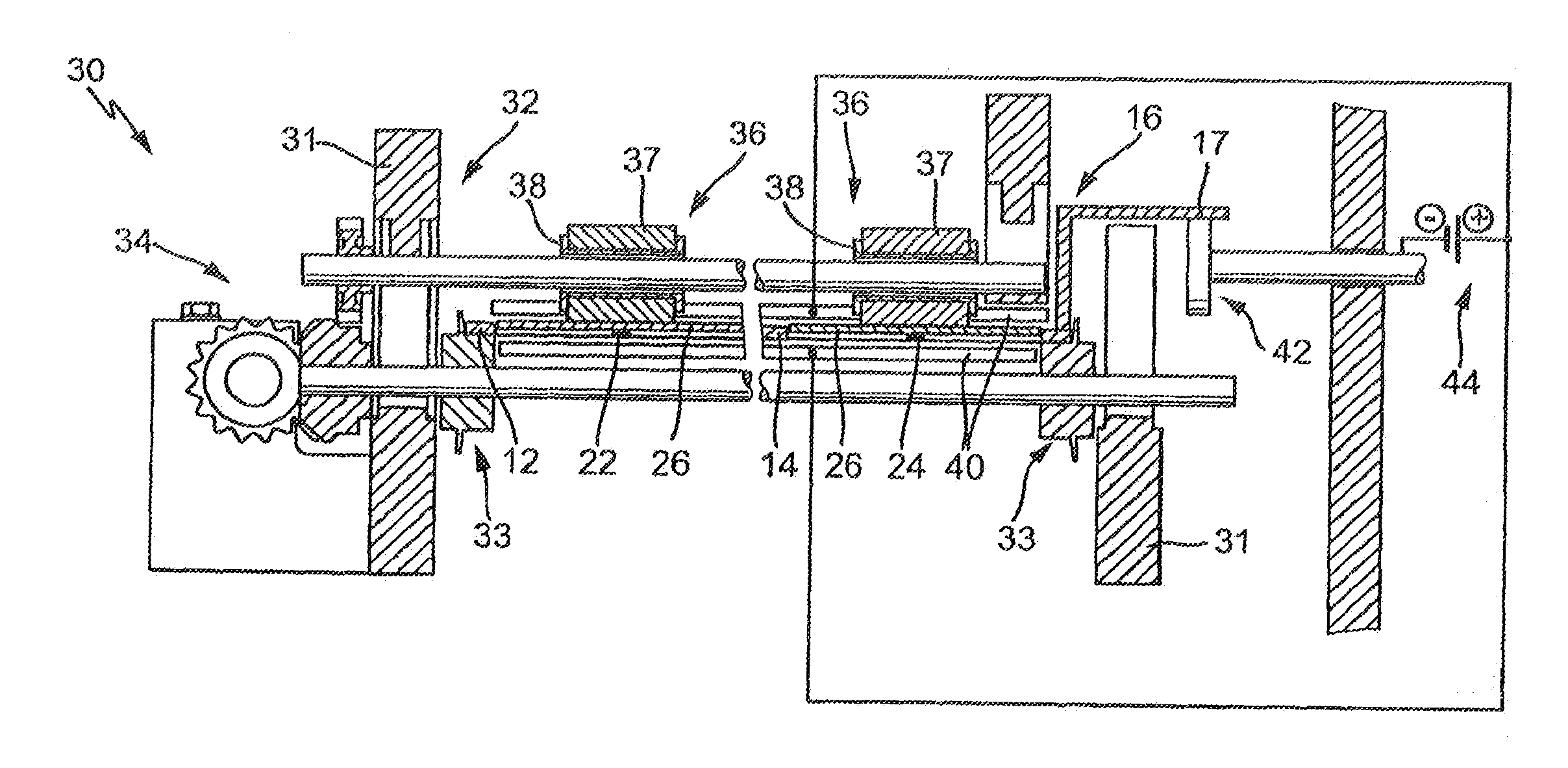
[0011]In a further development of the invention it is possible to construct the reception device in such a way that a substrate is sealingly located in a reception zone between adjacent frame pieces. Thus, all the reception zones of a reception device carry substrates and in this way form a substantially liquid-tight surface. The sealing or tightness requirements must at least be such that in the case of movement through the treatment medium or a liquid bath liquid does not penetrate from below through the areas between the substrate and the frame pieces, this applying in the case where the pressure of the liquid from below is only limited. For this purpose it is possible to have seals along the frame pieces or along the areas where the substrate sides are close to the frame pieces. This makes it possible to keep the top side of the substrates and also the reception device free from treatment liquid. This is especially advantageous if there is to be a treatment or coating only on the downwardly directed side of the substrates.
[0013]In a further development of the invention onto the reception device can be fixed a covering device or cover, particularly in a movable or articulated manner. Substrates placed in the reception device can be fixed by the cover or secured against dropping out or becoming detached. The cover can cover roughly the same surface area as the reception device. Advantageously it has a similar structure with pieces and interposed zones. Particularly advantageously it is constructed in a substantially similar or almost identical manner to the reception device. If the substrates are also held or secured from above in the reception device, easier movement thereof is possible and in particular can be held vertically or even rotated. If the cover is fixed at a number of points to the reception device, it can be made much thinner or weaker because it does not necessarily have to form an independently supporting structure. Its function is solely to hold the substrates in the reception zones of the reception device.

