Compliant electrical contact having maximized the internal spring volume

a technology of electrical contact and internal spring, which is applied in the direction of electrical testing, measurement devices, instruments, etc., can solve the problems of inability to utilize the maximum size spring within the spring probe, limited spring diameter, and attenuation of high frequency signals, so as to improve the ability to achieve high frequency and high current, the effect of increasing the internal spring volum

Inactive Publication Date: 2008-06-19
DELAWARE CAPITAL FORMATION INC
View PDF16 Cites 63 Cited by
  • Summary
  • Abstract
  • Description
  • Claims
  • Application Information

AI Technical Summary

Benefits of technology

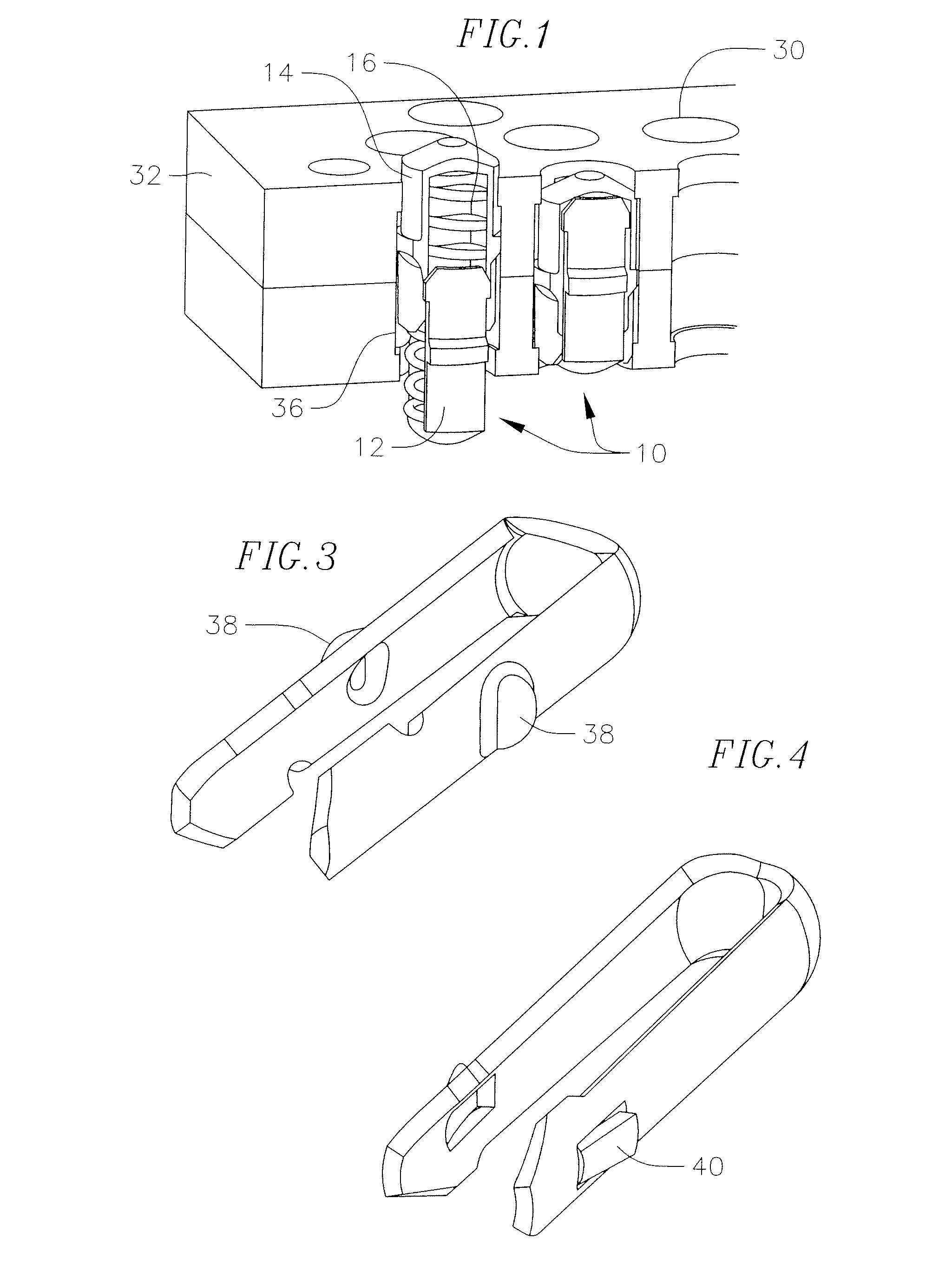
[0012]The present invention maximizes the internal spring volume by allowing for additional spring volume that is otherwise taken up by a smaller bore in one of the components such as in prior art designs. The present invention also improves on external spring and conventional spring probe contacts by enveloping the spring with an external shell formed by the two components allowing a shorter test height and having the connection points between the components at the closest point possible to the opposing tips, thereby improving on high frequency and high current capabilities. A further improvement over conventional spring probes is by providing up to eight points of contact that carry electrical current through the assembly versus one to three points by conventional spring probes.

Problems solved by technology

Consequently, this probe has a relatively long electrical interconnect length which may result in attenuation of the high frequency signals when testing integrated circuits.
A problem with conventional spring probes and shelled type spring probes is that because one component slides within the other component, the spring diameter is limited by the size of the smaller component which reciprocates within the second component, i.e. the plunger within the barrel.
Consequently, a maximize size spring cannot be utilized within the spring probe.

Method used


Image

  • Compliant electrical contact having maximized the internal spring volume
  • Compliant electrical contact having maximized the internal spring volume
  • Compliant electrical contact having maximized the internal spring volume

Examples


Embodiment Construction

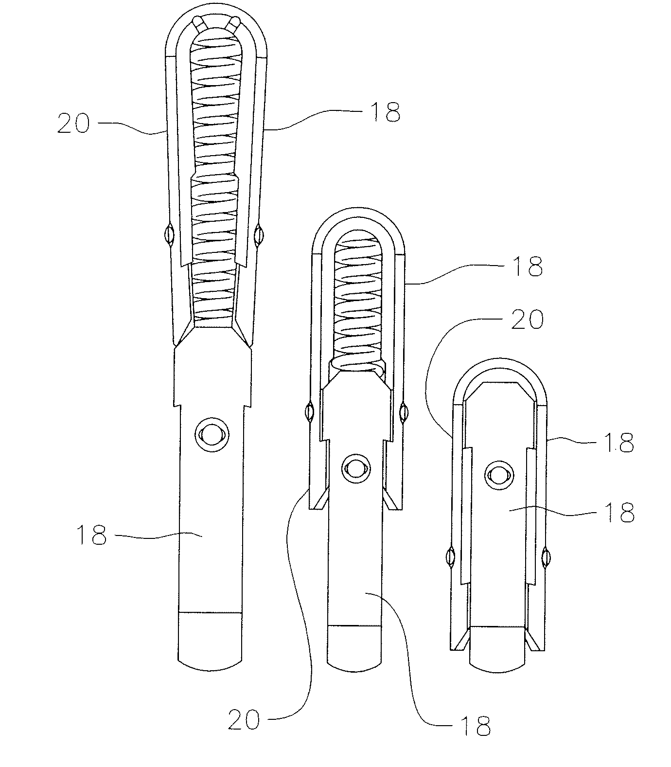
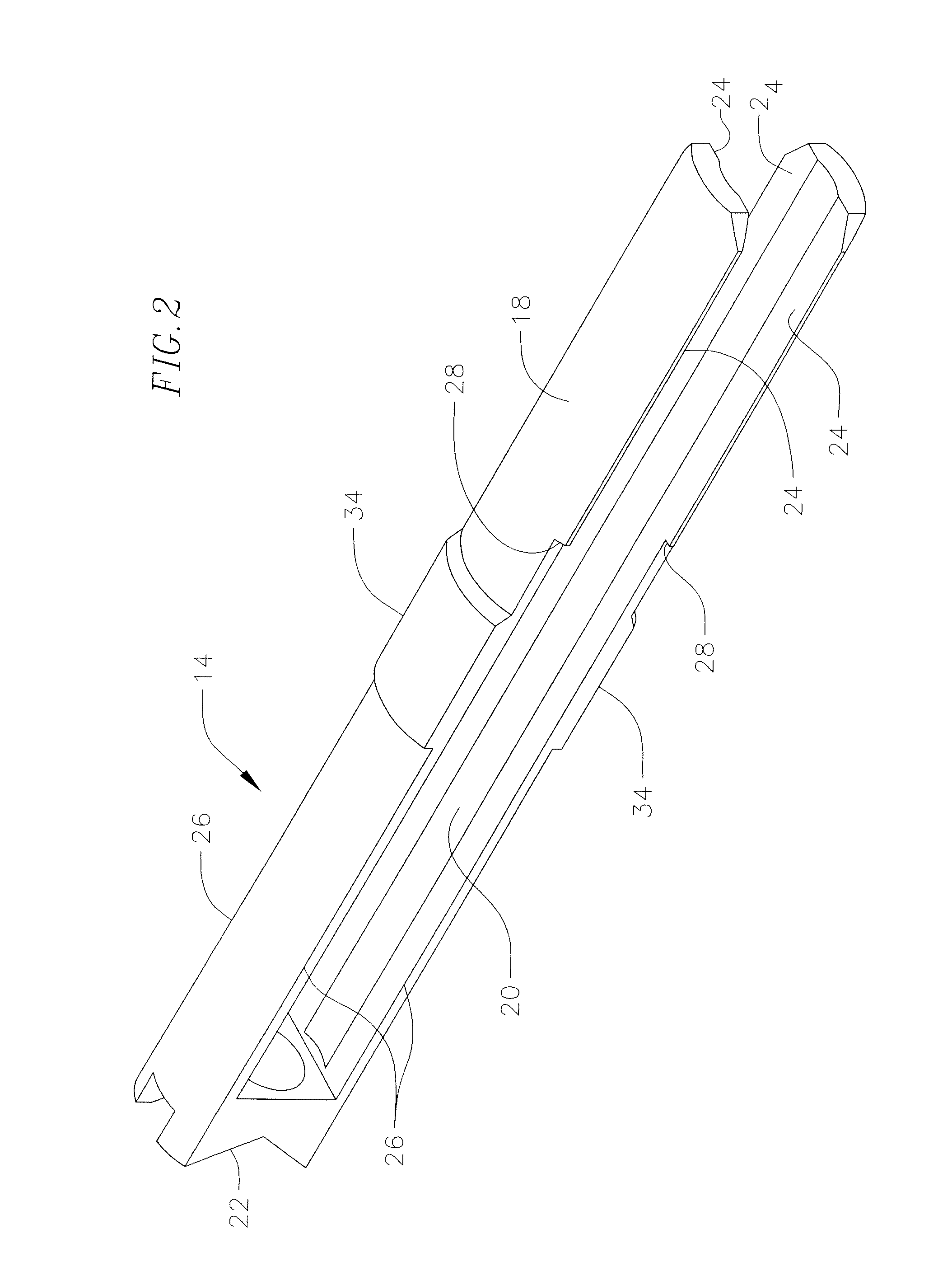
[0019]FIG. 1 illustrates the electrical contact 10 having maximized the internal spring volume of the present invention. The contact 10 consists of two identical components 12 and 14 which captivate a compression spring 16. Components 12 and 14 are axially aligned and rotated 90 degrees with respect to each other forming a generally enclosed internal volume which captivates the compression spring. As also shown in FIG. 2 which illustrates one of the components 14, each of the components is generally U-shaped having legs 18 and 20 and a contact portion 22. Each of the legs includes a sliding contact surface 24 which engages receiving surfaces 26. Sliding surface 24 and receiving surface 26 meet at a latch portion 28. Passing the opposing latches over each other locks the components together, preventing disassembly while allowing the contact surfaces to slide unopposed during operation. Once compressed to the normal operation height, the assembly forms a nearly enclosed shell. This de...


PUM


Abstract

A spring loaded electrical contact assembly for making a connection between two surfaces that consist of two U-shaped components axially opposed and rotated 90 degrees with respect to each other and configured to allow them to pass over each other while contacting in a wiping manner. When compressed to a test position, the components completely envelop a spring and provide a minimal solid height at maximum compliance while providing a low and reliable electrical contact.

Description

CROSS-REFERENCE TO RELATED APPLICATION(S)[0001]This application claims the benefit of U.S. Provisional Patent Application Ser. No. 60 / 875,048, filed Dec. 14, 2006 and entitled COMPLIANT ELECTRICAL CONTACT HAVING MAXIMIZED THE INTERNAL SPRING VOLUME, the entire content of which is hereby expressly incorporated by reference.FIELD OF THE INVENTION[0002]The present invention relates to electrical contact probes for forming electrical interconnects, and more particularly, to a compliant electrical contact probe assembly having two components with like sliding contact surfaces and latching geometry.BACKGROUND OF THE INVENTION[0003]Conventional spring-loaded contact probes generally include a moveable plunger, a barrel having and open end for containing an enlarged diameter section or bearing of the plunger, and spring for biasing the travel of the plunger in the barrel. The plunger bearing slideably engages the inner surface of the barrel. The enlarged bearing section is retained in the b...

Claims


Application Information

Patent Timeline
Patent Type & Authority Applications(United States)
IPC IPC(8): G01R1/067
CPCG01R1/06722
Inventor CHABINEAU-LOVGREN, SCOTT
Owner DELAWARE CAPITAL FORMATION INC
Why Eureka
Try Eureka