Current driving device

a driving device and current technology, applied in pulse generators, pulse techniques, instruments, etc., can solve the problems of difficult charging of current of nch transistors, insufficient capacity for charging/discharging voltage holding capacitance elements cb>1/b>, etc., to improve the non-uniformity of output currents and high speed

Active Publication Date: 2008-06-19
BISHOP DISPLAY TECH LLC
View PDF17 Cites 4 Cited by
  • Summary
  • Abstract
  • Description
  • Claims
  • Application Information

AI Technical Summary

Benefits of technology

[0015]An object of the present invention therefore is to provide a current driving device which can perform calibration at a high speed and improve the non-uniformity of the output currents even when a reference current is very small and when there is a change in the reference current.

Problems solved by technology

With this method, however, the capacity for charging / discharging the voltage holding capacitance element C1 becomes insufficient when the current value of the reference current source I1 is very small, so that it is difficult to charge the current of the Nch transistors QN1-QNm to accurately meet the value of the current from the reference current source I1 within the calibration period. FIG. 9 shows the state where the voltage holding capacitance element C1 is insufficiently charged because the reference current is very small.

Method used


Image

  • Current driving device
  • Current driving device
  • Current driving device

Examples


Embodiment Construction

[0055]Hereinafter, an embodiment of a current driving device according to the present invention will be described in detail by referring to the accompanying drawings. Same reference numerals are applied to the same or corresponding components within the drawings.

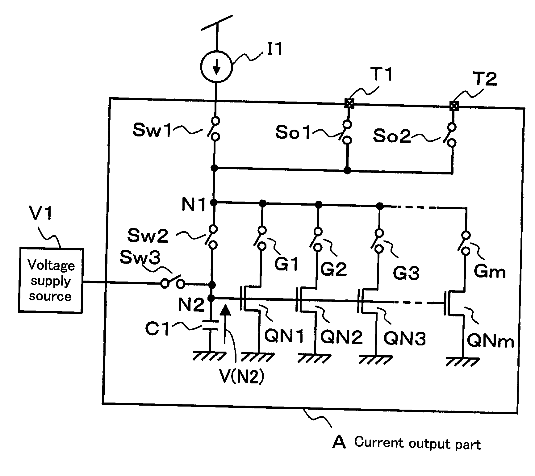
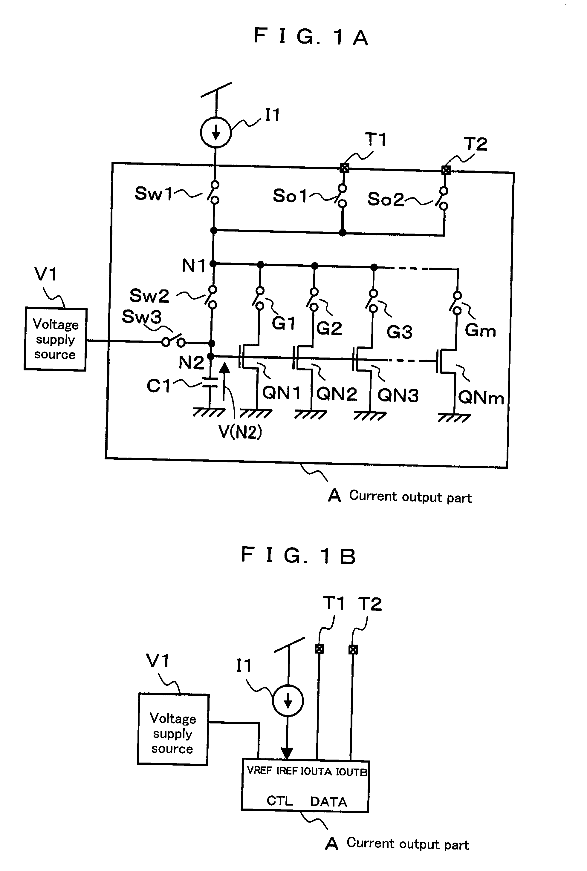
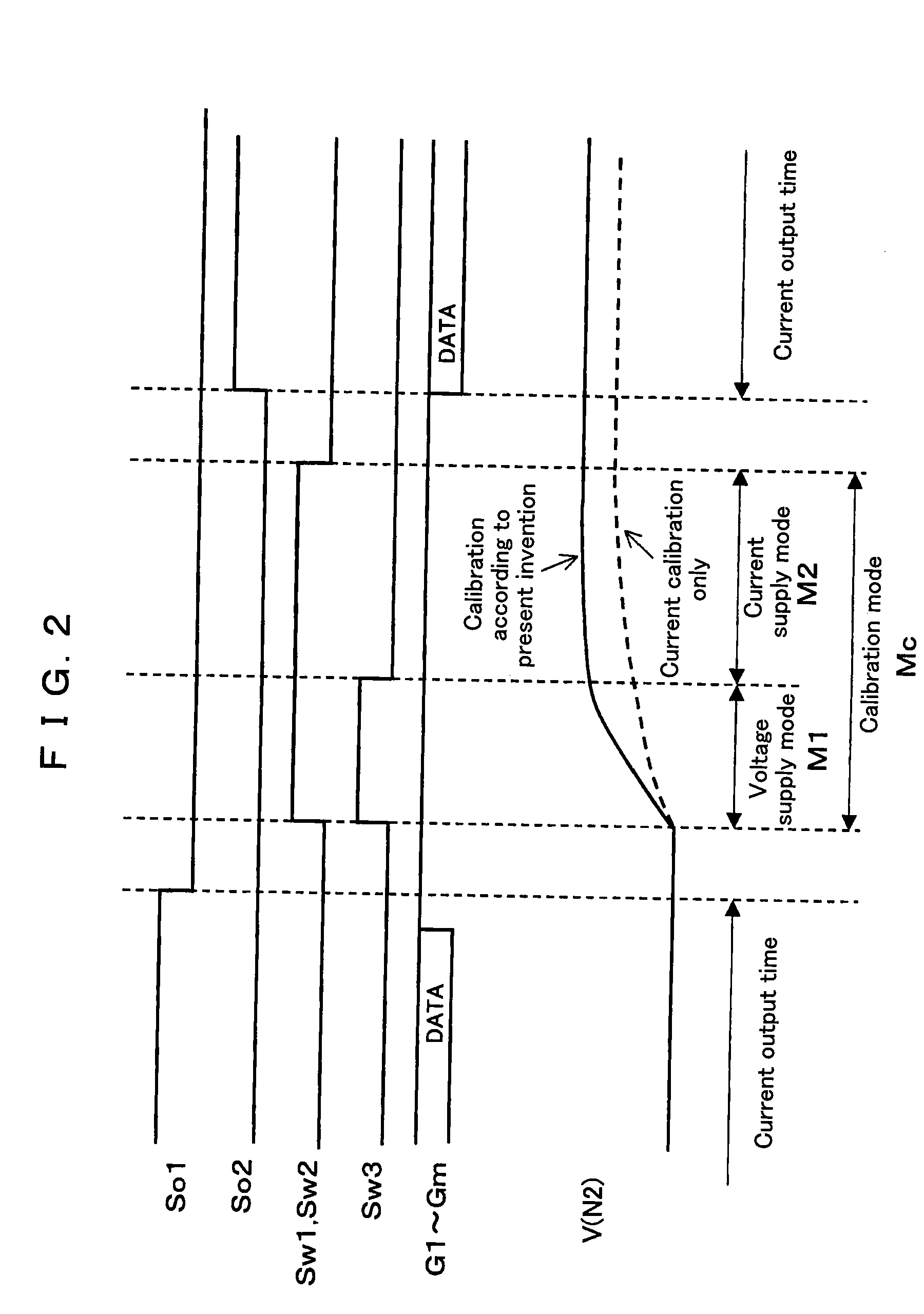
[0056]FIG. 1A is a circuit diagram for showing a structure of a current output part A that is mounted to a current driving device according to a preferred embodiment of the present invention, FIG. 1B is a block circuit diagram for showing the structure of the current output part A, FIG. 2 is a timing chart for describing actions of the current output part A, FIG. 3 is a block circuit diagram for showing the overall structure of the current driving device, and FIG. 4 is a circuit diagram for showing an embodiment of a voltage supply source V1.

[0057]

[0058]First, the current output part A will be described by referring to FIG. 1A and FIG. 1B. One end of a voltage holding capacitance element C1 is connected to a ground terminal,...


PUM


Abstract

A current driving device comprises: a voltage supply part; a current supply part; and a plurality of current output parts, each comprising a current-voltage converting function, a voltage-current converting function, and a voltage holding capacitance element. The current output part takes three operation modes. Under a voltage supply mode, the current output part receives a voltage from the voltage supply part and holds the voltage in the voltage holding capacitance element. Under a current supply mode, the current output part receives the current from the current supply part, generates a second voltage by the current-voltage converting function and holds the voltage in the voltage holding capacitance element. Under a current output part, the current output part outputs an output current according to the voltage held in the voltage holding capacitance element by the voltage-current converting function. By charging the current output part with the reference voltage before the calibration performed by using the reference current, calibration of the current output part is performed at a high speed.

Description

FIELD OF THE INVENTION[0001]The present invention relates to a current driving device used preferably as a driver for displays such as organic EL (Electro-luminescence) panels, LED panels, and the like.BACKGROUND OF THE INVENTION[0002]Recently, flat-panel displays have a larger screen and higher definition, while establishing reduction in thickness, weight, and cost. With such backgrounds, it is required for display drivers to improve the uniformity in the displayed image qualities through decreasing variations between output electric currents that are outputted from output terminals. Variations in the electric currents in static actions of current mirrors include variations caused due to fabrication processes of each transistor, variations of gate voltages caused due to resistances of power supply wirings, and the like. Further, variations due to dynamic actions of the current mirrors include variations caused due to injection of electric charges from a display panel or instantaneo...

Claims


Application Information

Patent Timeline
Patent Type & Authority Applications(United States)
IPC IPC(8): G05F1/10
CPCG05F3/26
Inventor MIZUKI, MAKOTONISHI, KAZUYOSHIOHMORI, TETSUROKOJIMA, TOMOKAZUKOJIMA, HIROSHI
Owner BISHOP DISPLAY TECH LLC
Why Eureka
Try Eureka