Method for producing a composite structure

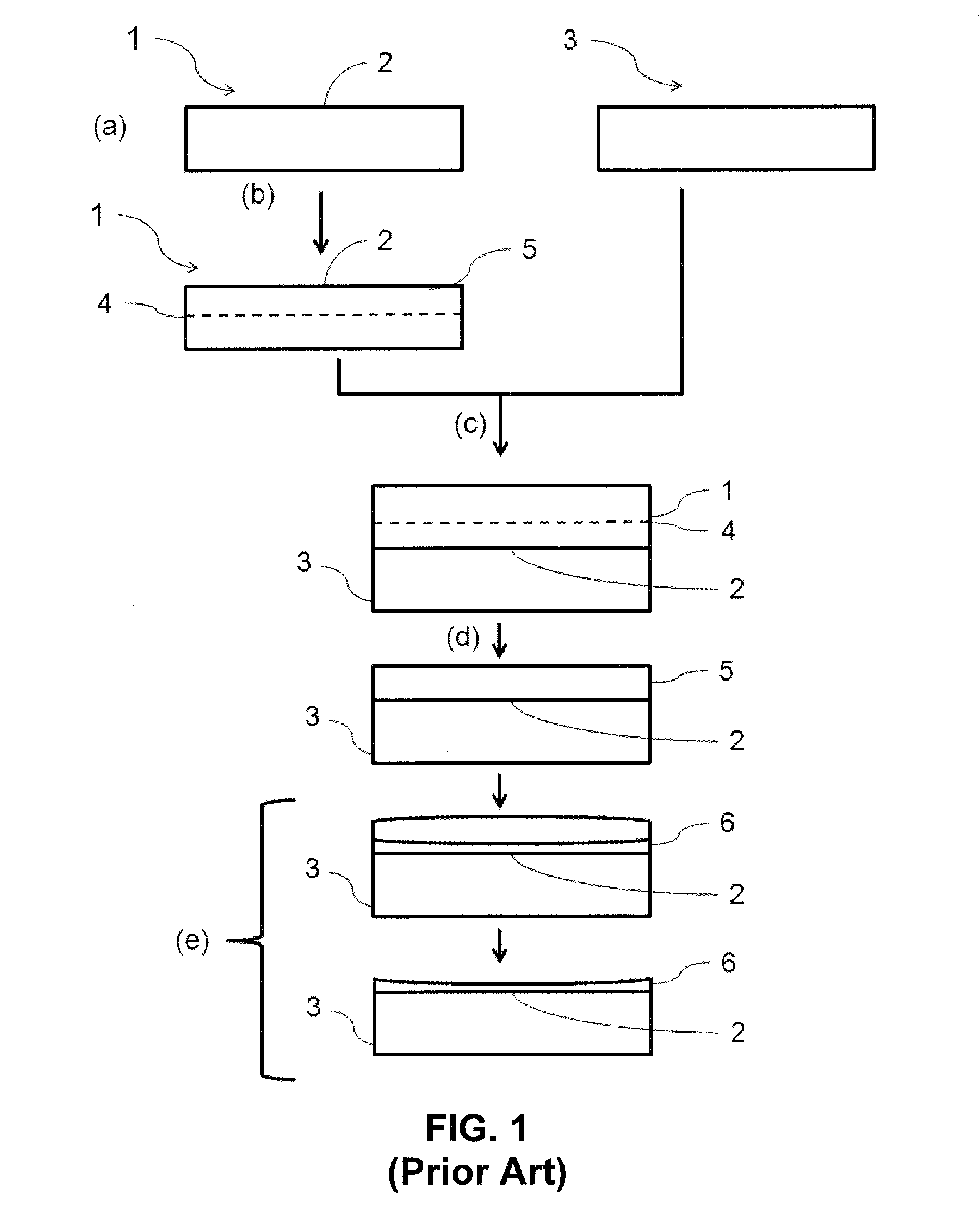
a composite structure and manufacturing method technology, applied in the direction of basic electric elements, semiconductor/solid-state device manufacturing, electric devices, etc., can solve the problems of difficult control of the thickness of the thinned working layer b>6/b> on the conclusion of all the stages of the manufacturing process, and achieve the effect of reducing the thickness

Active Publication Date: 2016-12-22
S O I TEC SILICON ON INSULATOR THECHNOLOGIES
View PDF6 Cites 3 Cited by
  • Summary
  • Abstract
  • Description
  • Claims
  • Application Information

AI Technical Summary

Benefits of technology

[0031]Thus, the excess dose of implanted species in the central part of the zone of weakening makes it possible to obtain a rounded thickness profile of the working layer on conclusion of stage d). Consequently, the thickness profile of the thinned working layer is substantially constant over the whole of the extent of the thinned layer.
[0032]According to one embodiment, the layer of oxide formed during stage e) exhibits a lower thickness in its central part and a greater thickness on proceeding toward the annular periphery of the la...

Problems solved by technology

However, the main disadvantage related to this manufacturing process of the state of the art is that the thinned working layer 6 exhibits a nonuniformity in thickness.
This is, in particular, damaging for the manufacture of structures of the silicon-on-...

Method used


Image

  • Method for producing a composite structure
  • Method for producing a composite structure
  • Method for producing a composite structure

Examples


first embodiment

of Stage b)

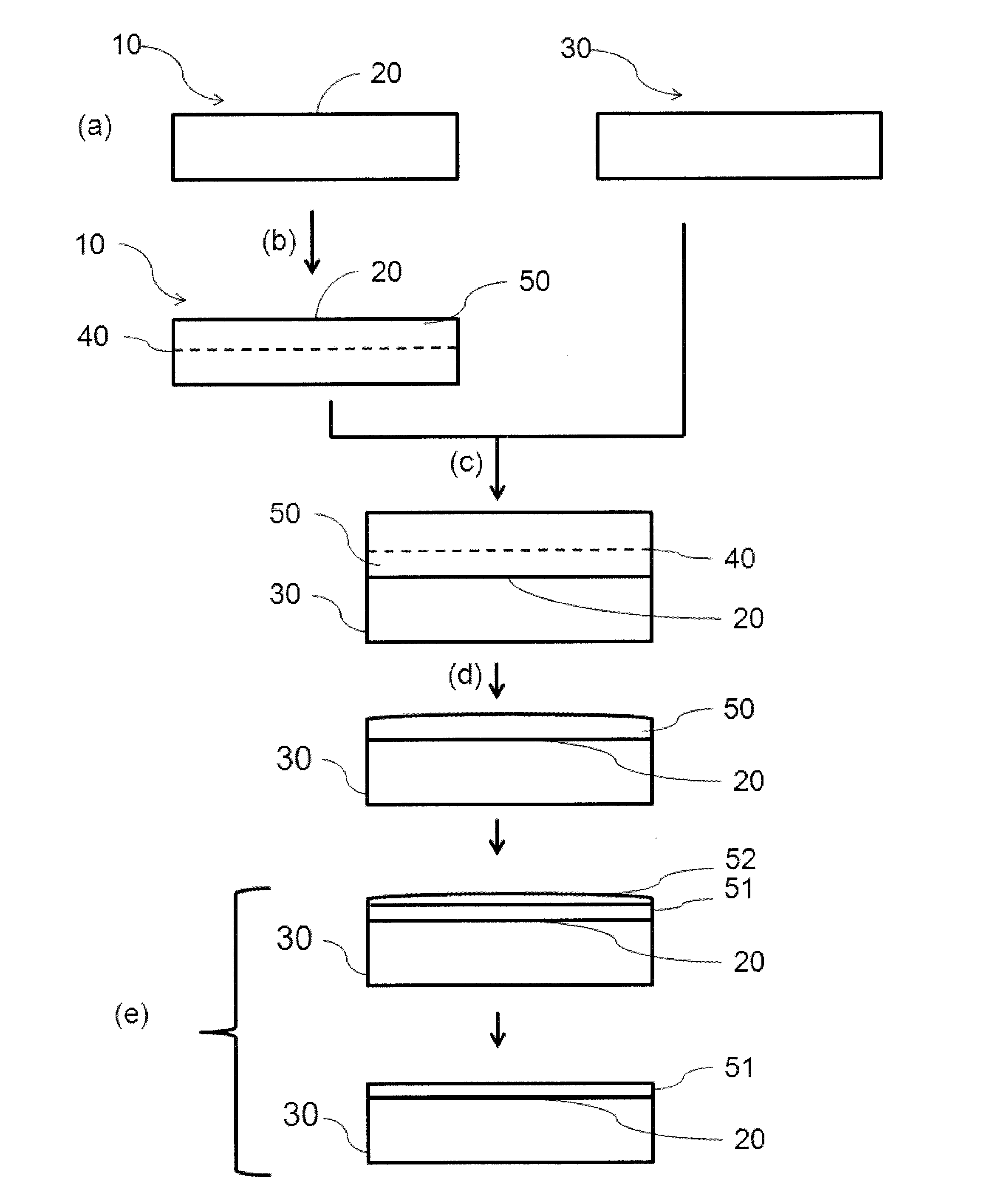
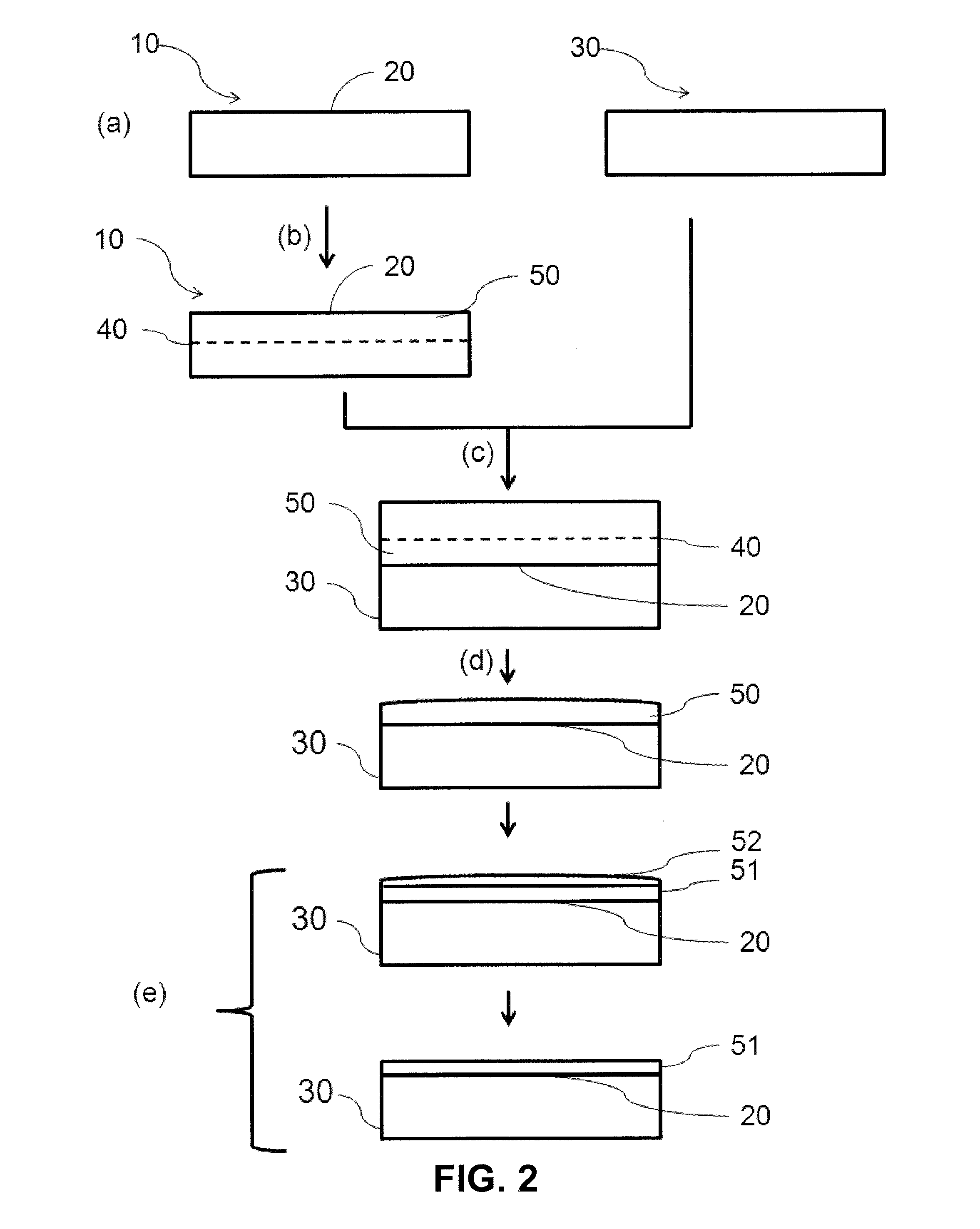
[0080]According to a first embodiment, the formation of the zone of weakening 40 is carried out by implantation of at least one of the species chosen from: hydrogen ions or helium ions. The total dose of the implanted species is nonuniform over the extent of the zone of weakening 40 and the nonuniformity of the dose of the implanted species is appropriate for generating the nonuniform thickness profile of the working layer 50 on conclusion of the fracturing stage d).

[0081]The term “dose of implanted species” is understood to mean the amount of implanted species per unit of surface area of the zone of weakening 40. The dose of implanted species is measured in atoms per cm2.

[0082]The implantation stage is advantageously carried out by a single wafer implant device. In contrast to batch wafer implant devices, a single wafer implant device makes it possible to implant a nonuniform dose of species over the whole of the extent of the zone of weakening 40.

[0083]It has been found...

second embodiment

of Stage b)

[0093]According to a second embodiment, stage b) is carried out in two stages:[0094]First implantation of species: according to a first implantation energy, the dose of the first implantation of species being nonuniform over the extent of the zone of weakening 40.[0095]Second implantation of species: according to a second implantation energy lower than the first implantation energy, the dose of the second implantation of species being nonuniform over the extent of the zone of weakening 40.

[0096]The second implantation energy is greater than 90% of the first implantation energy. The dose of the first implantation of species and the dose of the second implantation of species are complementary over the whole of the extent of the zone of weakening 40. The nonuniformity in the dose of the first implantation of species and the nonuniformity in the dose of the second implantation of species are appropriate for generating the thickness profile of the working layer 50 on conclusio...


PUM


Abstract

A process for the manufacture of a composite structure includes the following stages: a) providing a donor substrate comprising a first surface and a support substrate; b) forming a zone of weakening in the donor substrate, the zone of weakening delimiting, with the first surface of the donor substrate, a working layer; c) assembling the support substrate and the donor substrate; d) fracturing the donor substrate along the zone of weakening; and e) thinning the working layer so as to form a thinned working layer. Stage b) is carried out so that the working layer exhibits a thickness profile appropriate for compensating for the nonuniformity in consumption of the working layer during stage e).

Description

CROSS-REFERENCE TO RELATED APPLICATIONS[0001]This application is a national phase entry under 35 U.S.C. §371 of International Patent Application PCT / FR2014 / 051487, filed Jun. 17, 2014, designating the United States of America and published as International Patent Publication WO 2014 / 207346 A1 on Dec. 31, 2014, which claims the benefit under Article 8 of the Patent Cooperation Treaty and under 35 U.S.C. §119(e) to French Patent Application Serial No. 1301528, filed Jun. 28, 2013, the disclosure of each of which is hereby incorporated herein in its entirety by this reference.TECHNICAL FIELD[0002]This disclosure relates to a process for the manufacture of a composite structure.BACKGROUND[0003]A process for the manufacture of a composite structure, known from the state of the art and illustrated in FIG. 1, comprises the following stages:[0004]a) Providing a donor substrate 1 comprising a first surface 2, and a support substrate 3;[0005]b) Forming a zone of weakening 4 in the donor subst...

Claims


Application Information

Patent Timeline
IPC IPC(8): H01L21/762H01L21/02
CPCH01L21/02236H01L21/76254H01L21/30604
Inventor BEN MOHAMED, NADIAMAZE, ERIC
Owner S O I TEC SILICON ON INSULATOR THECHNOLOGIES
Why Eureka
Try Eureka