

Liquid crystal display device with plastic substrate
- Summary
- Abstract
- Description
- Claims
- Application Information
AI Technical Summary
Benefits of technology
Problems solved by technology
Method used
Image

Examples
Embodiment Construction
Hereinafter, a preferred embodiment of the present invention will be described with reference to the accompanying drawings.
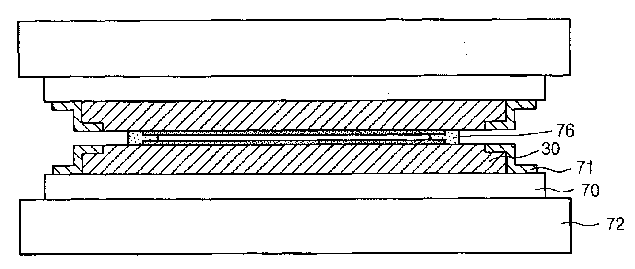
Referring to FIGS. 3A and 3B, a plastic substrate 30 includes a thin edge groove 31 along edges thereof. The substrate 30 has a thickness t1 of 200 to 700 μm, and the edge groove 31 has a depth t2 which is a half of the thickness of the substrate 30. In this embodiment, the depth t2 of the edge groove 31 should be bigger than the thickness of the heat resistant fixing tape or the substrate fixing device which will be explained below. The edge groove 31 can be formed at any side of the substrate 30 including long sides and short sides, and can be formed at all four sides.
Further, as shown in FIG. 3A, the edge groove 31 can be formed at an edge of the substrate 30 in a continuous groove configuration, and as shown in FIG. 3B, can be formed at a desired portion of the edge in the substrate 30 in an interrupted groove configuration.
The edge groove 31 has a width W1 ...
PUM
 Abstract
Description
Claims
Application Information