Fixed pattern noise compensation method and apparatus

a compensation method and fixed pattern technology, applied in the field of image signal processing, can solve the problems of fixed pattern noise, fixed pattern noise, inconsistencies in physical properties, etc., and achieve the effect of minimizing processing tim

Inactive Publication Date: 2008-06-19
HAND HELD PRODS
View PDF99 Cites 16 Cited by
  • Summary
  • Abstract
  • Description
  • Claims
  • Application Information

AI Technical Summary

Benefits of technology

[0018]The scene of uniform radiance to which a pixel array is exposed is preferably a gray scale uniform radiance scene, that is, a scene which does not result either in a maximum clipped or minimum clipped pixel value being read from the pixels in the pixel array. By providing a uniform radiance scene yielding gray scale pixel values between these two limits, the problem of measurement clipping is avoided.
[0023]In the present invention, gray scale correction values can be stored in predetermined memory locations of the imaging system. Preferably, so that processing time is minimized, the correction terms are read from memory and used to correct pixel values in the case of decoding applications only when stored pixel values are read from memory during execution of a decoding algorithm. An advantage of the compensation method of the present invention is that the method of the present invention allows correction values to be selected between a large number of discrete values, without requiring the providing of costly and space consuming physical elements as in the prior art design. The correction method of the present invention may be used in combination with a hardware implemented compensation scheme.

Problems solved by technology

Fixed pattern noise can result from a variety of sources.
For example fixed pattern noise can result from inconsistencies in the physical properties of electrical components of the image sensor such as switching components associated with each pixel, or in certain types of image sensors with column amplifiers associated with each column.
Fixed pattern noise can also result from certain illumination apparatus configurations.
If the illumination is characteristically non-uniform, but its characteristics are fixed each time data is captured, then fixed pattern noise results.

Method used


Image

  • Fixed pattern noise compensation method and apparatus
  • Fixed pattern noise compensation method and apparatus
  • Fixed pattern noise compensation method and apparatus

Examples


Embodiment Construction

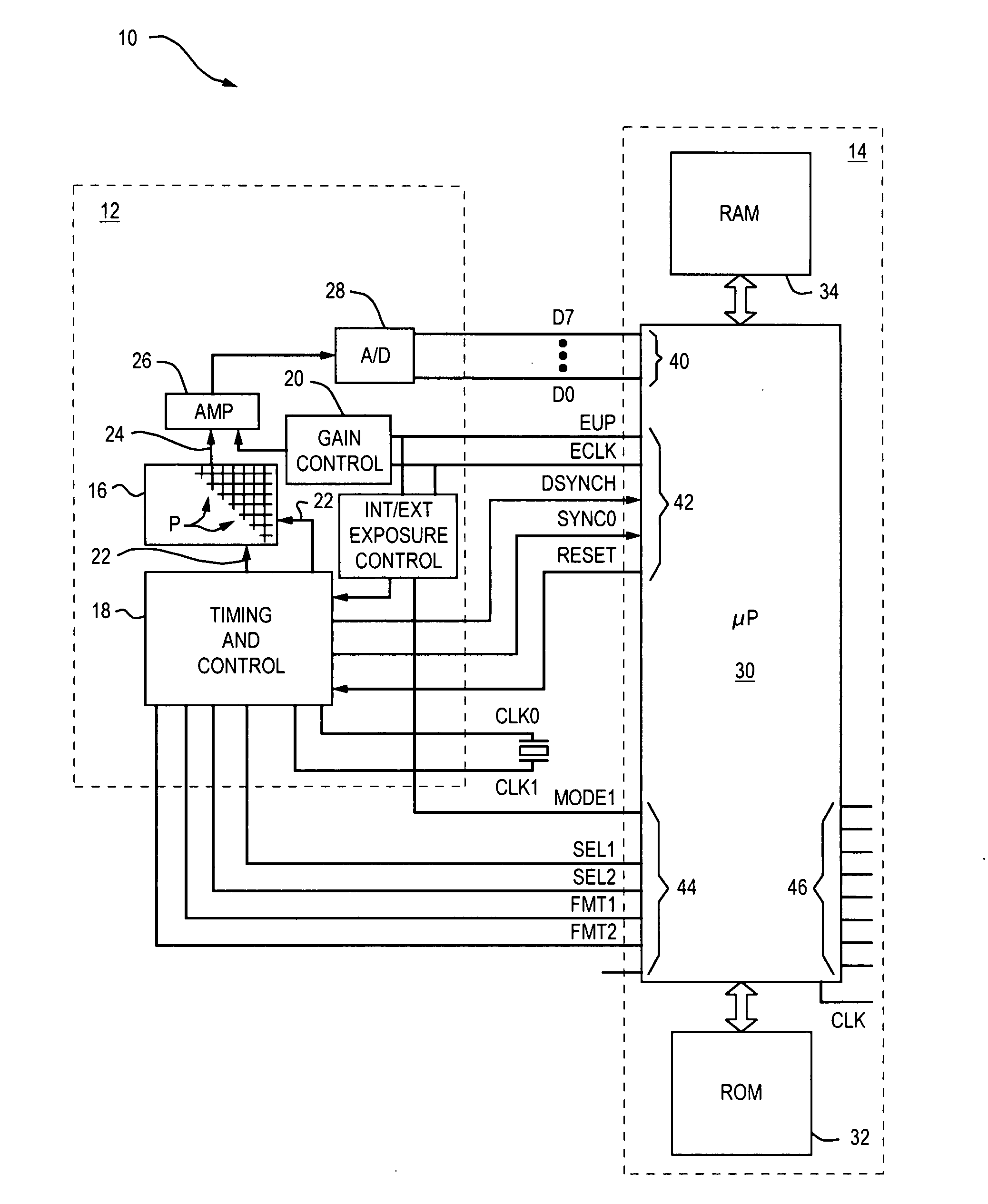
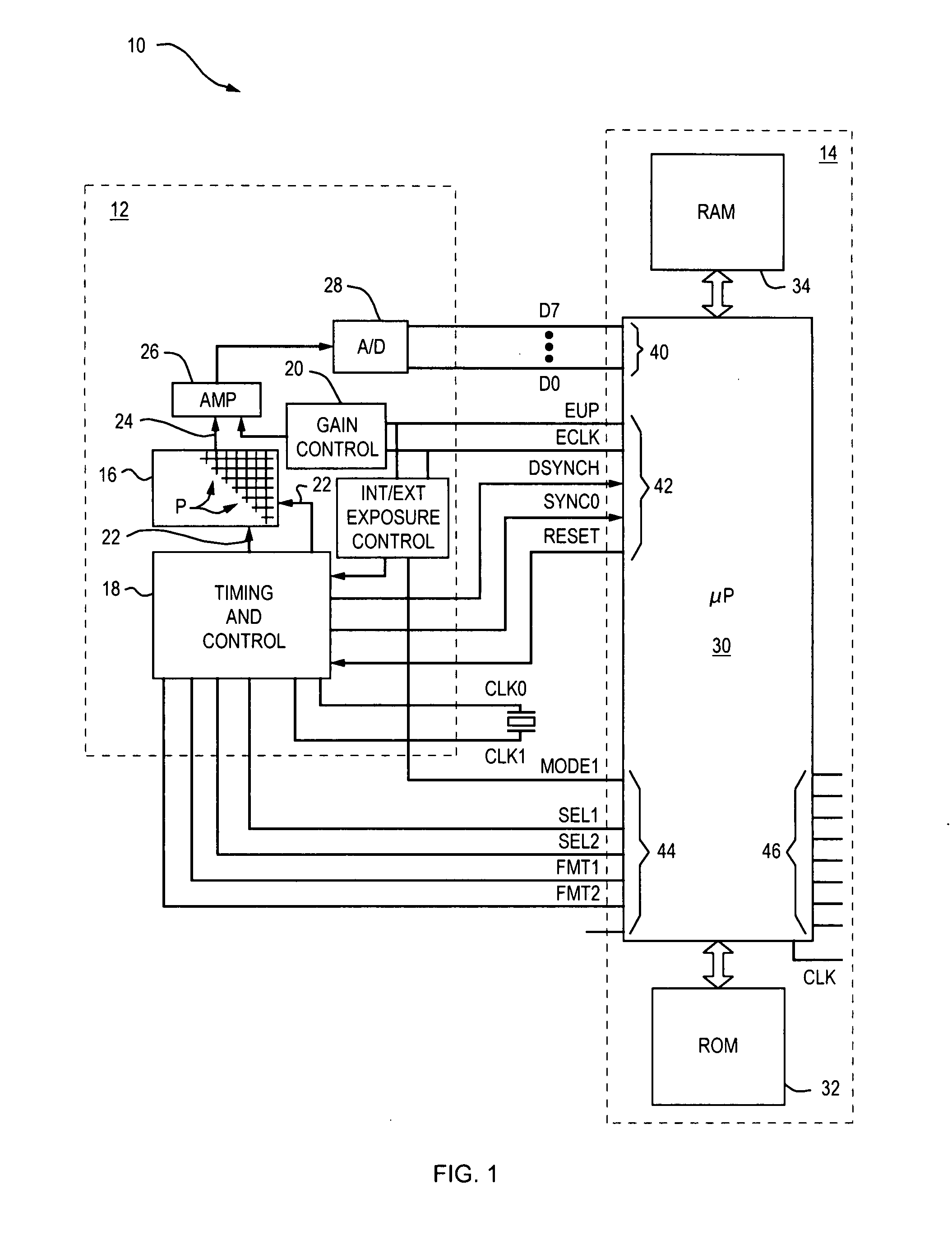
[0034]An imaging system 10 having an image sensor 12 and control processor 14 in which the present invention may be incorporated is shown in FIG. 1.

[0035]Image sensor 10 includes, on a single substrate a two dimensional array 16 of light sensitive picture elements, or pixels upon which an optical system is arranged to focus an image of indicia and further includes a timing and control circuit 18 for electrically addressing pixels P via horizontal and vertical address lines 20 and 22, thereby causing electrical signals representing the image to be read out of array 16 via output 24 thereof. After amplification by amplifier 26, and conversion by analog-to-digital converter 28 the latter signals are output from chip 12 as serial digital parallel image data signals on lines D0=D7 or as a digital serial image data signal on data lines D0-D1.

[0036]Digital image data is supplied from sensor 12 to processor 14 with the aid of a first signal known as a frame start pulse and a second signal k...


PUM


Abstract

The invention relates to a method and apparatus for configuring an imaging system to compensate for fixed pattern noise, variations in pixel values captured from an image sensor that vary according to a fixed pattern. In a method for configuring an imaging system for compensating an additive term component of fixed pattern noise, a pixel array is exposed to a scene of known radiance and an average white value is determined for each pixel of an array. Each average white value is compared to a predetermined reference value to determine a correction value for each pixel. In a method for configuring an imaging system for compensating both an additive and multiplicative component of fixed pattern noise, a pixel array is exposed to a first scene having a first known radiance, and frames of the scene are captured, and then the array is exposed to a second scene having a second known radiance and frames of the second scene are captured. After first and second average white values are determined for each pixel additive and multiplicative term correction values for each pixel are then determined by solving for a system of equations relating the first and second average white values and first and second scene radiances. Correction values can be utilized to correct pixel values of a frame of image data, and a decoding algorithm for attempting to decode a frame of image data including corrected pixel values can be activated.

Description

CROSS REFERENCE TO RELATED APPLICATIONS[0001]This application is a continuation of U.S. patent application Ser. No. 08 / 828,340 filed Mar. 28, 1997 entitled, “Method and Apparatus For Adjusting Pixel Values In An Imaging System.” The priority of the above application is claimed and the above application is incorporated herein by reference.BACKGROUND OF THE INVENTION[0002]1. Field of the Invention[0003]The invention relates generally to image signal processing and in particular to a method and apparatus for compensating for fixed pattern noise in image sensor image signals.[0004]2. Background of the Prior Art[0005]When pixel values, representative of pixel voltages are read from an image sensor pixel array, slight inconsistencies are observable between the voltages of the various pixels even when the array is exposed to a scene of uniform radiance. The inconsistency in the pixel values read from the various pixels is commonly referred to as “noise” either of a fixed pattern noise type...

Claims


Application Information

Patent Timeline
Patent Type & Authority Applications(United States)
IPC IPC(8): H04N5/217G06K9/00H04N5/365H04N5/369
CPCH04N5/2176H04N5/3651H04N5/76H04N5/2173H04N5/3658H04N25/63H04N25/671H04N25/677H04N25/60
Inventor HUSSEY, ROBERT M.HAVENS, WILLIAM H.
Owner HAND HELD PRODS
Why Eureka
Try Eureka