
Image processor and image processing program

a technology which is applied in the field of image processing and image processing program to achieve the effect of small circuit siz

Active Publication Date: 2008-06-19
OLYMPUS CORP
View PDF7 Cites 30 Cited by
  • Summary
  • Abstract
  • Description
  • Claims
  • Application Information

AI Technical Summary

Benefits of technology

The invention is an image processor that can correct the spatial frequency band of an input image by applying a plurality of band correction means with different characteristics. The processor uses a feature quantity computation means to figure out the direction of an edge in the image, and a synthesis means to combine the outputs of the band correction means based on the feature quantity. The processor can also determine the weight for each band correction means based on the feature quantity and the characteristics of the imaging system. The technical effects of the invention include improved band enhancement processing in optical systems with different characteristics, reduced circuit size, improved reliability, and the ability to stave off failures in band correction processing caused by noise or image deficiencies.

Problems solved by technology

Still, many contrivances have been proposed so far in the art because of difficulty obtaining the best results depending on various subjects.
However, such prior arts say nothing about contrivances made from the standpoints that when the optimum band enhancement is applied to a subject, it adapts well to various image capturing conditions, and it is implemented in much smaller circuit size.

Method used


Image

  • Image processor and image processing program
  • Image processor and image processing program
  • Image processor and image processing program

Examples


Embodiment Construction

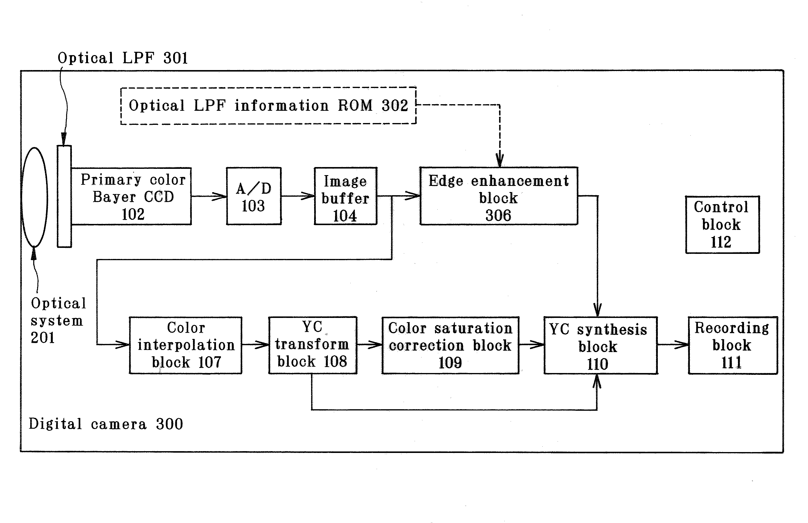
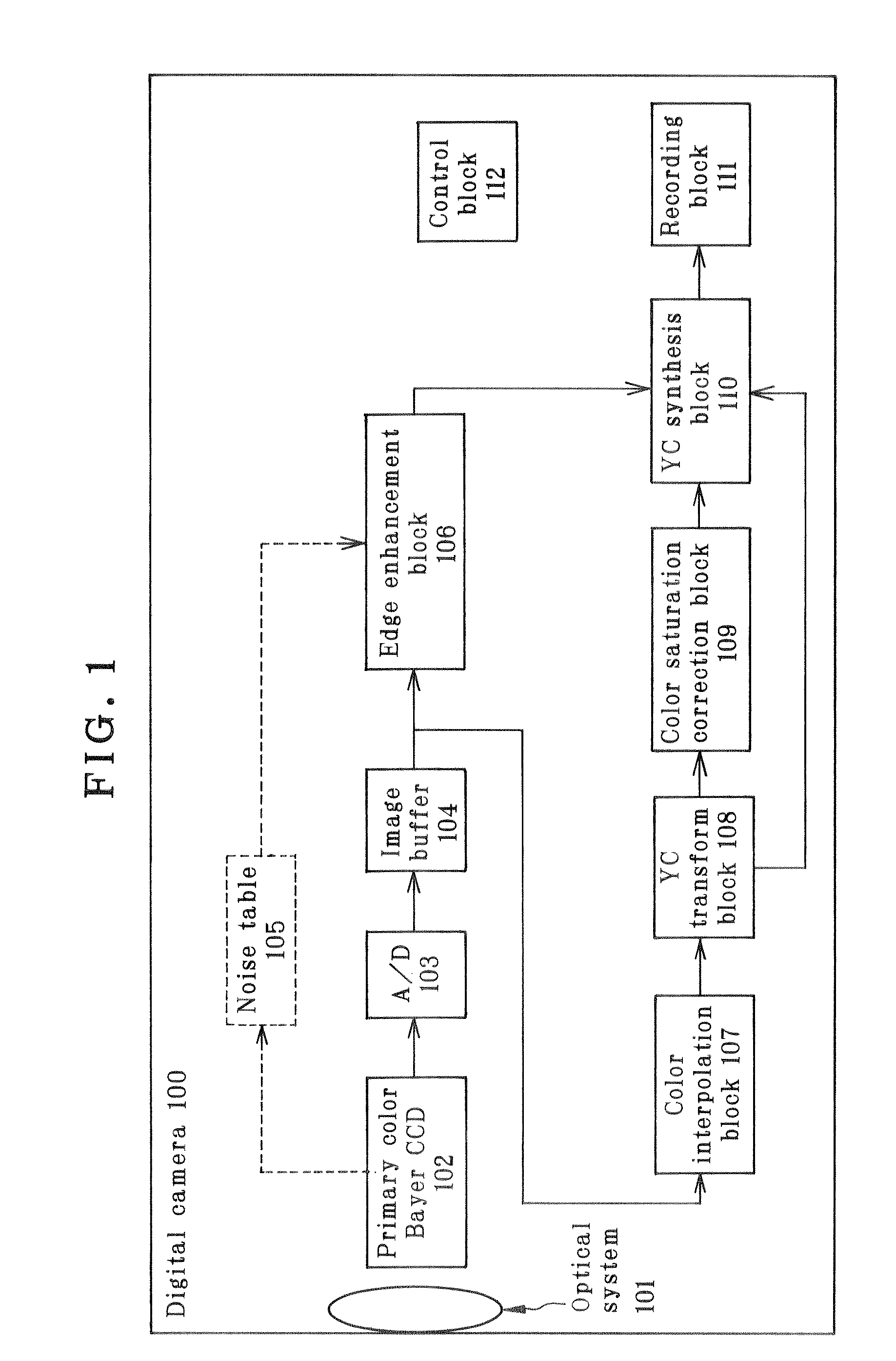
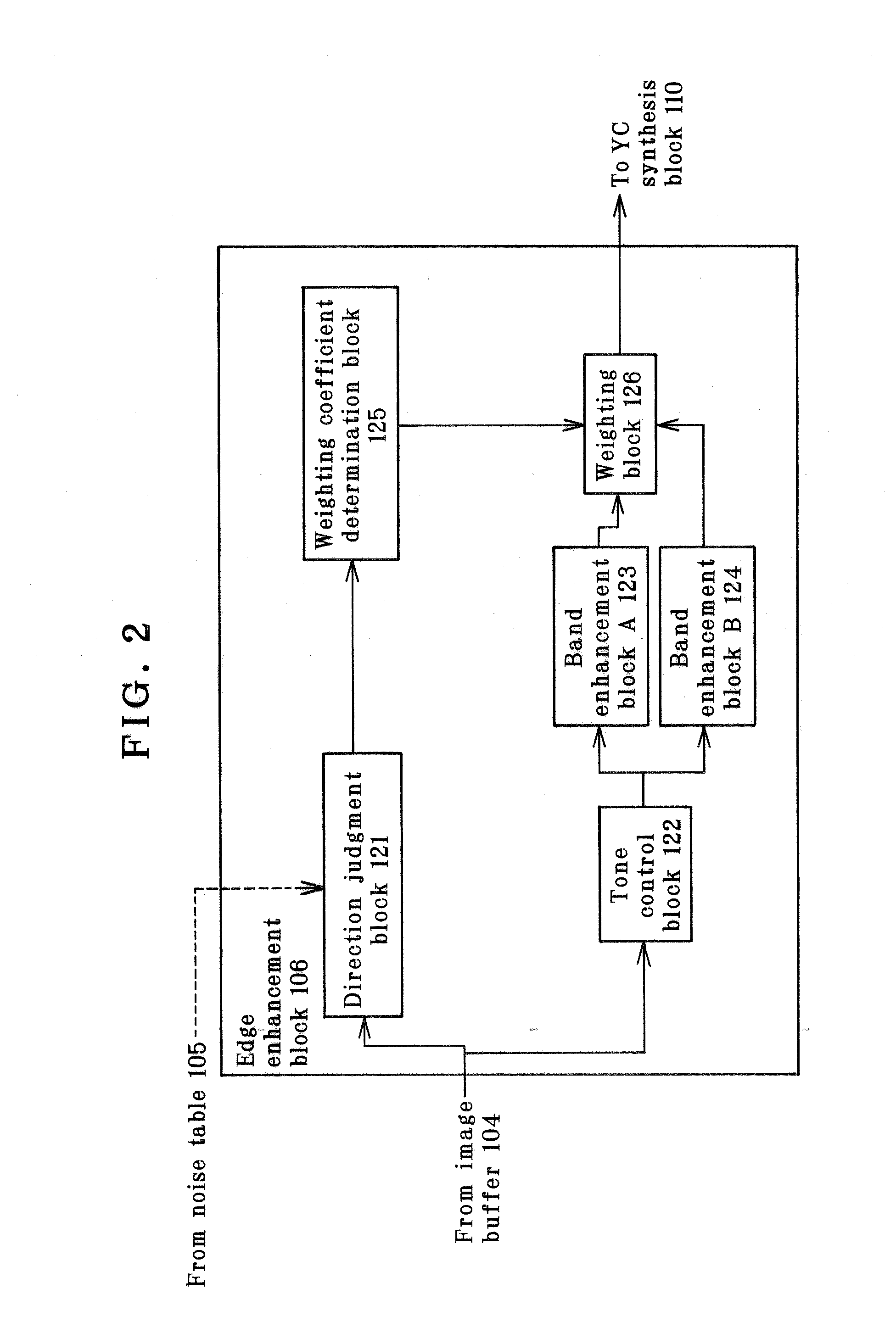
[0047]Some embodiments of the invention are now explained with reference to the accompanying drawings. FIGS. 1 to 9 are illustrative of the first embodiment of the invention. FIG. 1 is illustrative of the architecture of the first embodiment; FIG. 2 is illustrative of the setup of the edge enhancement block in FIG. 1; FIGS. 3 and 4 are illustrative of the operation of the direction judgment block in FIG. 1; FIG. 5 is illustrative of the noise table in FIG. 1; FIG. 6 is illustrative of the enhancement characteristics of the band enhancement block in FIG. 1; FIG. 7 is illustrative of one exemplary weight; FIG. 8 is a flowchart of the RAW development software in the first embodiment; and FIG. 9 is a flowchart of how to figure out the edge component in FIG. 8.

[0048]The architecture of the first embodiment according to the invention is shown in FIG. 1. The embodiment here is a digital camera shown generally by 100 that is built up of an optical system 101, a primary color Bayer CCD 102, ...


PUM


Abstract

The digital camera (100) has an image processor that corrects an input image for a spatial frequency band. The edge enhancement block (106) computes an edge component for band correction. A signal interpolated at color interpolation block (107) to make compensation for a color component missing from each pixel of a single-chip image is then converted at YC transform block (108) into a luminance signal and a color difference signal after tone correction, the luminance and color signals sent out to YC synthesis block (110) and color saturation correction block (109), respectively. Then, the color saturation correction block (109) controls the color saturation of the color difference signal to send it out to YC synthesis block (110). At the same time, the edge component computed at edge enhancement block (106) is sent out to YC synthesis block (110), too.

Description

TECHNICAL ART[0001]The present invention relates to an image processor and image processing program for applying the optimum edge enhancement to a subject.BACKGROUND ART[0002]Commonly for image processing systems mounted in digital cameras or the like, frequency-band enhancement processing is applied so as to give the final image sharpness. The simplest approach to the band enhancement processing is to rely on only one band enhancement filter having fixed characteristics. Still, many contrivances have been proposed so far in the art because of difficulty obtaining the best results depending on various subjects.[0003]Further, JP(A)2002-344743 discloses an example of analyzing a half tone structure in an image to control an enhancement filter depending on a screen angle. Furthermore, Japanese Patent No. 2858530 sets forth a method for generating an edge component on the basis of the results of analysis in an edge direction such that there are much less fluctuations along the edge dire...

Claims


Application Information

Patent Timeline
Patent Type & Authority Applications(United States)
IPC IPC(8): H04N5/00G06K9/40G06T5/20H04N1/409H04N5/205H04N5/232
CPCG06T5/20H04N1/4092H04N1/6027G06T2207/20192H04N9/646G06T5/003G06T2207/10024H04N9/045H04N23/843H04N25/134G06T5/73
Inventor TSUKIOKA, TAKETO
Owner OLYMPUS CORP
Learn More