X-ray computed tomography apparatus

a computed tomography and x-ray technology, applied in tomography, applications, instruments, etc., can solve the problems of x-ray ct apparatus, two-dimensional x-ray area detectors have a tendency to need a new added value, etc., to optimize eliminate slicing artifacts, and optimize the effect of spatial resolution or image nois

Inactive Publication Date: 2008-06-19
GE MEDICAL SYST GLOBAL TECH CO LLC
View PDF14 Cites 39 Cited by
  • Summary
  • Abstract
  • Description
  • Claims
  • Application Information

AI Technical Summary

Benefits of technology

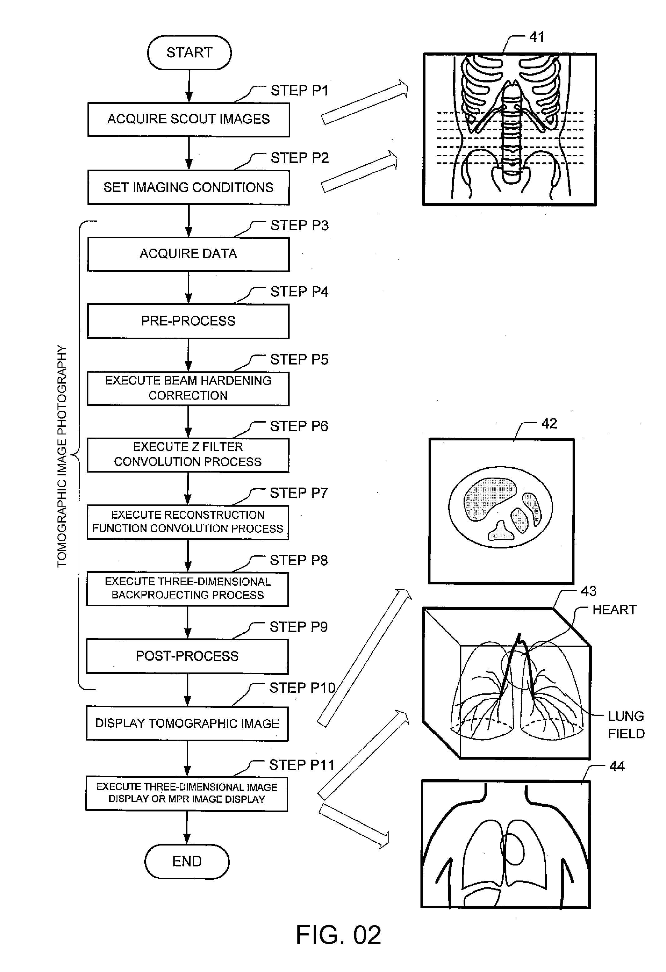
[0035]In the X-ray CT apparatus according to the thirteenth aspect, when a conventional scan or a cine scan is effected on the tomographic images indicative of the X-ray tube voltage-dependent information at a plurality of z-direction coordinate positions of the subject, the tomographic images at the plural z-direction coordinate positions are shifted or displaced within a tomographic image plane, i.e., an xy plane due to respiration, beat or the like of the subject. When the tomographic images indicative of the X-ray tube voltage-dependent information are three-dimensionally displayed or MPR (Multi Plain Reformat)-displayed, splicing for a z-direction conventional (axial scan) or cine scan might be viewed. That is, since the tomographic images at the original plural X-ray tube voltages are shifted in the x or y direction upon photography at the plural z-direction coordinate positions, the slicing appears as slicing artifacts. In order

Problems solved by technology

However, the X-ray CT apparatus using the two-dimensional X-ray area detector has a tendency to need a new added value like a so-called dual energy scan in addition to the conventional im

Method used


Image

  • X-ray computed tomography apparatus
  • X-ray computed tomography apparatus
  • X-ray computed tomography apparatus

Examples


second embodiment

[0104]This is an embodiment in which imaging conditions and image reconstructing conditions for a plurality of X-ray tube voltage-based tomographic images are adjusted in such a manner that an index value corresponding to a target for image quality is given to each tomographic image subjected to the dual energy scan and its index value is satisfied.

third embodiment

[0105]This is an embodiment in which when a mis-registration artifact is found in each tomographic image subjected to a dual energy scan, a registration or alignment correction is done to optimize the image quality of the tomographic image subjected to the dual energy scan to targeted image quality, i.e., an index value.

fourth embodiment

[0106]This is an embodiment in which when mis-registration or displacement (displacement in xy plane) in a tomographic-image plane direction is detected at a tomographic image subjected to a dual energy scan or upon a three-dimensional display or an MPR display, processing is returned to image reconstruction of a plurality of X-ray tube voltage-based tomographic images to perform their displacement corrections and plural X-ray tube voltage-based image reconstruction is redone, thereby optimizing the quality of each tomographic image subjected to the dual energy scan, the quality of a three-dimensionally displayed image, and the quality of an MPR-displayed image.


PUM


Abstract

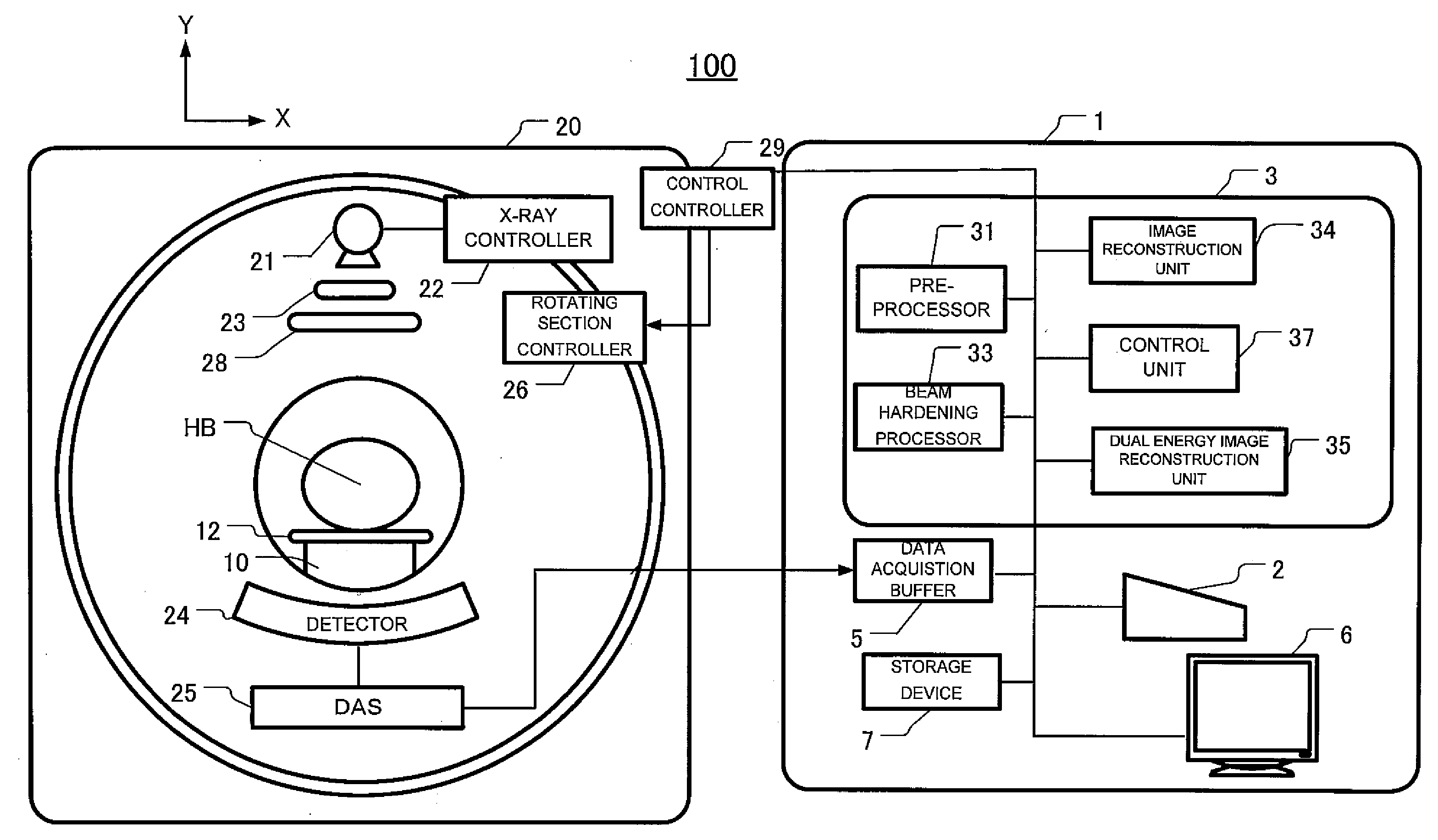
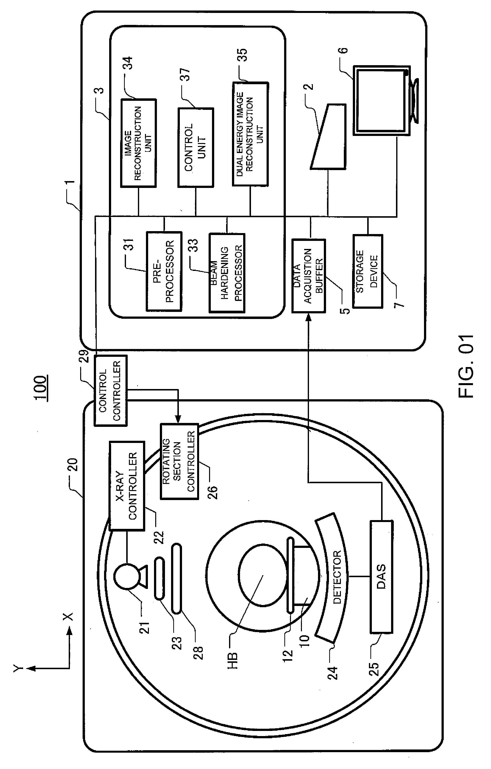
The present invention provides an X-ray CT apparatus capable of improving image quality of a dual energy image. The X-ray CT apparatus comprises an X-ray tube for applying X rays having a first energy spectrum and X rays having a second energy spectrum different from the first energy spectrum to a subject, an X-ray data acquisition unit for acquiring X-ray projection data of the first energy spectrum projected onto the subject and X-ray projection data of the second energy spectrum projected thereonto, dual energy image reconstructing unit for image-reconstructing tomographic images indicative of X-ray tube voltage-dependent information at X-ray absorption coefficients related to a distribution of atoms, based on the X-ray projection data of the first energy spectrum and the X-ray projection data of the second energy spectrum, and adjusting unit for adjusting conditions for the image reconstruction in order to optimize the tomographic images indicative of the X-ray tube voltage-dependent information.

Description

CROSS REFERENCE TO RELATED APPLICATIONS[0001]This application claims the benefit of Japanese Patent Application No. 2006-339313 filed Dec. 18, 2006.BACKGROUND OF THE INVENTION[0002]The present invention relates to techniques of an X-ray CT apparatus which optimizes spatial resolution and image noise of two-dimensional distribution tomographic images indicative of X-ray tube voltage-dependent information at X-ray absorption coefficients related to a distribution of atoms, tomographic images subjected to a so-called dual energy scan in a medical X-ray CT (Computed Tomography) apparatus or the like, and of an X-ray CT image reconstructing method used therefor.[0003]In an X-ray CT apparatus using a two-dimensional X-ray area detector, tomogram imaging based on a low X-ray tube voltage and a high X-ray tube voltage has heretofore been performed upon obtaining tomographic images of a two-dimensional distribution of given atoms as shown in FIG. 4 to thereby obtain a tomographic image at th...

Claims


Application Information

Patent Timeline
IPC IPC(8): A61B6/03
CPCA61B6/4035A61B6/405A61B6/583A61B6/027A61B6/542
Inventor NISHIDE, AKIHIKOGOHNO, MAKOTO
Owner GE MEDICAL SYST GLOBAL TECH CO LLC
Why Eureka
Try Eureka