Sintered Material, Ferrous Sintered Sliding Material, Producing Method of the Same, Sliding Member, Producing Method of the Same and Coupling Device

a technology of ferrous sintered sliding material and producing method, which is applied in the direction of shaft and bearing, bearing components, bearings, etc., can solve the problems of inability to prolong a lubrication interval or eliminate and achieve the effect of prolonging a lubrication interval, excellent seizing resistance and abrasion resistance, and eliminating the necessity of lubricating

Inactive Publication Date: 2008-06-19
KOMATSU LTD
View PDF5 Cites 61 Cited by
  • Summary
  • Abstract
  • Description
  • Claims
  • Application Information

AI Technical Summary

Benefits of technology

[0014]Accordingly, an object of the present invention is to provide a sintered material, a ferrous sintered sliding material, a producing method of the same, a sliding member, a producing method of the same and

Problems solved by technology

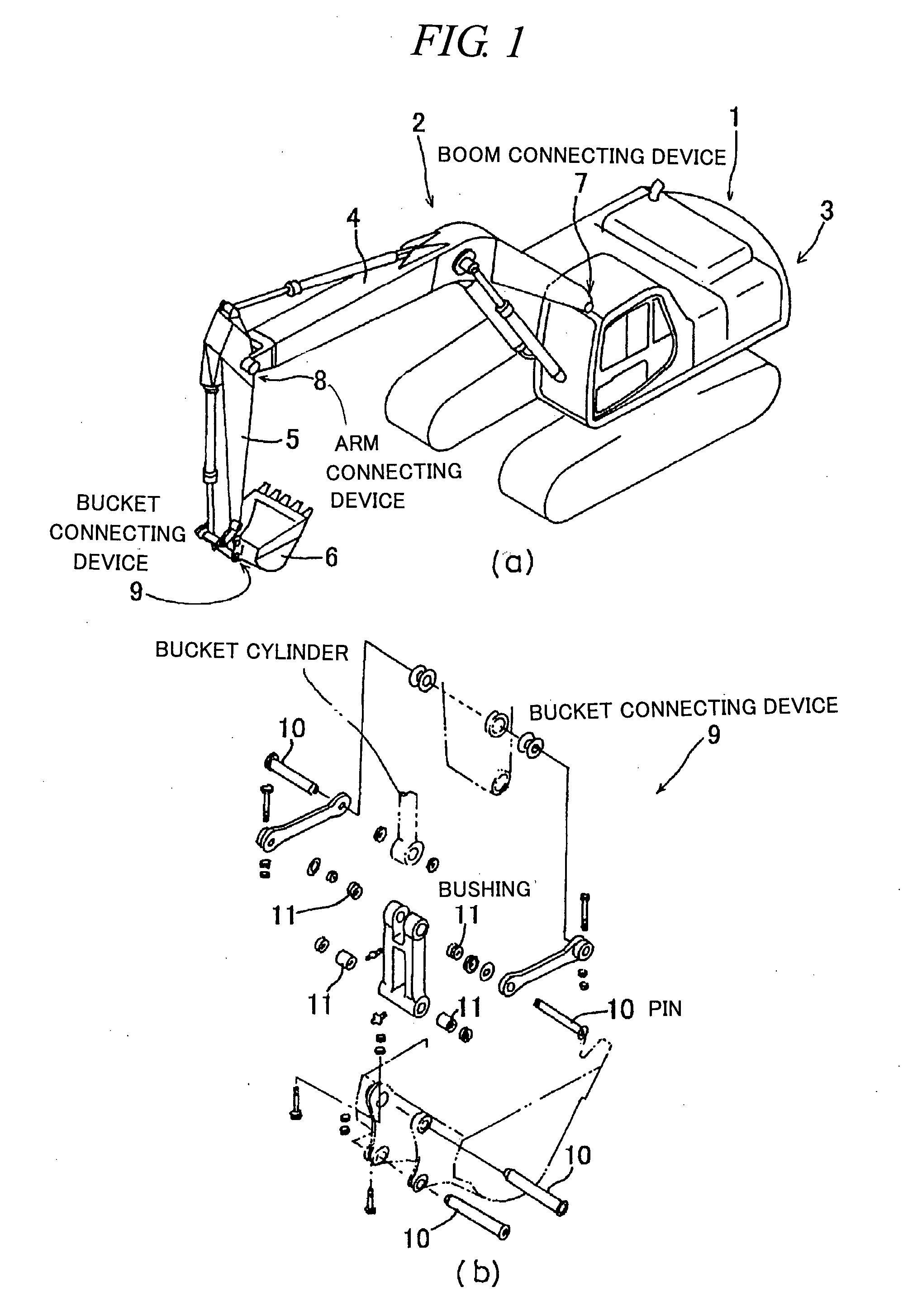
A conventionally used sintered sliding material such as a connecting device used under severe sliding conditions such as a high-bearing stress, slow-speed sliding and oscillating condition ha

Method used


Image

  • Sintered Material, Ferrous Sintered Sliding Material, Producing Method of the Same, Sliding Member, Producing Method of the Same and Coupling Device
  • Sintered Material, Ferrous Sintered Sliding Material, Producing Method of the Same, Sliding Member, Producing Method of the Same and Coupling Device
  • Sintered Material, Ferrous Sintered Sliding Material, Producing Method of the Same, Sliding Member, Producing Method of the Same and Coupling Device

Examples


example 1

Preliminary Test

[0165]In this test, using various types of high speed steel powder (M2) having composition of Fe-16 wt % Al-25 wt % Cu, Fe-50 wt % Al, Fe-16 wt % Al under #200 mesh and Fe-0.9 wt % C-5 wt % Mo-6 wt % W-1 wt % V having an average grain size of 16 μm; iron powder under #300 mesh (ASC300, manufactured by Hoganas); electrolytic copper powder (CE15, manufactured by FUKUDA METAL FOIL POWDER Co., Ltd.); graphite powder having an average grain size of 6 μm (KS6, manufactured by LONZA Group Ltd,); Sn powder under #250 mesh; TiH powder under #300 mesh; Fe-25 wt % P powder; Mo powder having an average grain size of 5 μm; Ni powder under #350 mesh; and Mn powder, various types of alloy shown in Tables 1 and 2 were prepared. Each of the alloys was formed into a test piece, shown in FIG. 5, at forming pressure of 5 ton / cm2 and then vacuum sintered for 1 hour at each temperature within 1000 to 1200° C. And, after cooling under N2 gas of 600 torr, each sintered compact was examined ...

example 2

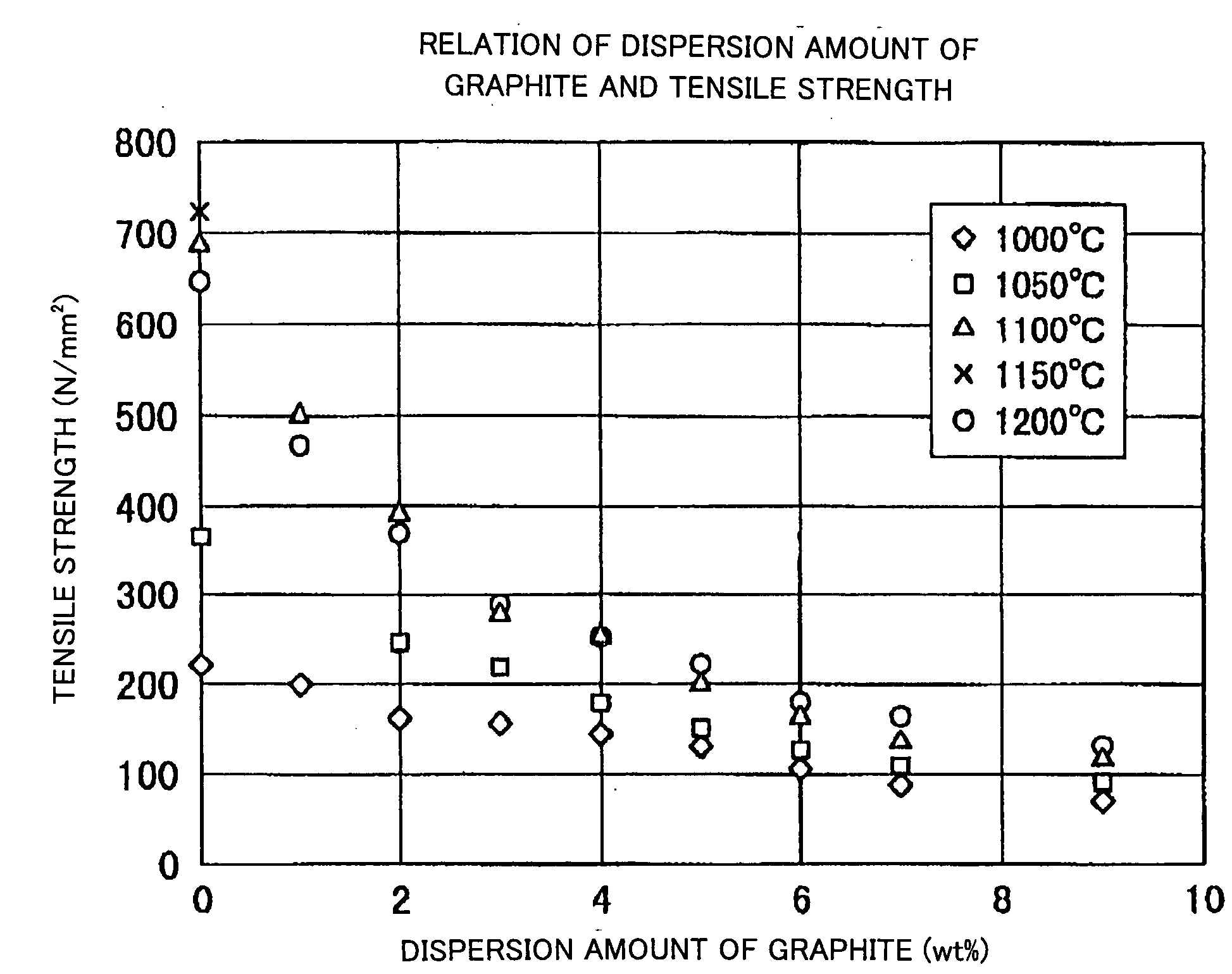
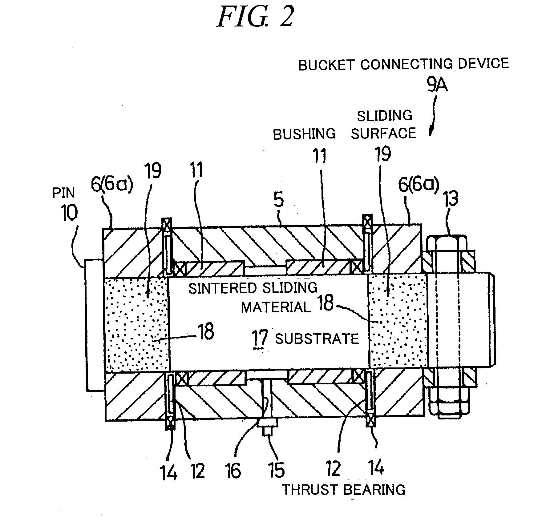
[0187]In this Example, by using Fe—Cu based alloy powder shown in Table 3, each of copper powder of 10 wt %, graphite particle (KS6 as described above) of 1 to 9 wt %, granulated powder of KS6 (a grain size of 0.05 to 1 mm), Mo having an average grain size of 5 μm, MoS2 and BN each having an average grain size of 15 μm, shown in Table 4, was mixed and formed into a test piece under the same condition as Example 1. And, each test piece was vacuum sintered at 1050 to 1200° C. and then machined into a bushing for bearing test as shown in FIG. 20. Then, the bushing was vacuum impregnated with engine oil of W30 and subjected to a bearing test. The bearing test was carried out under a condition where lubricating oil can be retained in 8% by volume or more. And, MoS2 is previously mixed with graphite in equal amount (wt %) in order to prevent reaction of MOS2 at sintering.

TABLE 3COMPOSITION OF Fe—Cu ALLOY POWDER FOR BEARING TEST (wt %)CCuAlSiMnNiCrMoW(A)Fe16Al25Cu024.815.90.110.31————(B)Fe...


PUM

PropertyMeasurementUnit
Grain sizeaaaaaaaaaa

Abstract

The iron-based sintered sliding material comprises: a sintered structure which contains 10-50 wt. % copper and 1-15 wt. % carbon and has been formed by sintering a powder mixture obtained by mixing at least one of an Fe—Cu alloy powder containing copper in an amount which is the solid solubility or larger and is 5-50 wt. %, excluding 50 wt. %, and an Fe—Cu—C alloy powder containing copper in an amount which is the solid solubility or larger and is 5-50 wt. %, excluding 50 wt. %, and containing carbon in an amount of 0-5 wt. %, excluding 0 wt. %, with a graphite powder and at least one of a copper powder and a copper alloy powder; and graphite particles dispersed in the sintered sliding material in an amount of 1-14 wt. % or 3-50 vol. %.

Description

FIELD OF THE INVENTION[0001]The present invention relates to a sintered material, a ferrous sintered sliding material, a producing method of the same, a sliding member, a producing method of the same and a coupling device. Particularly, it relates to a sintered material, a ferrous sintered sliding material, a producing method of the same, a sliding member, a producing method of the same and a coupling device having excellent seizing resistance and abrasion resistance and providing self-lubricating property so as to prolong a lubrication interval or eliminate the necessity of lubricating.BACKGROUND OF THE INVENTION[0002]As a bearing available with a long lubrication interval or without lubricating, an oil retaining bearing composed of a copper based or ferrous porous sintered alloy retaining lubricating oil in the pores (for example, referring to nonpatent literature 1) and a self-lubricating sliding material in which a solid lubricant such as graphite, MoS2, WS2 and the like is disp...

Claims


Application Information

Patent Timeline
IPC IPC(8): F16C33/12C22C33/02
CPCB22F3/1035C22C33/0278F16C33/12F16C33/103F16C33/102F16C33/121
Inventor TAKAYAMA, TAKEMORI
Owner KOMATSU LTD
Why Eureka
Try Eureka