
Air fuel ratio control apparatus for an internal combustion engine

Inactive Publication Date: 2008-06-26
MITSUBISHI ELECTRIC CORP
View PDF0 Cites 40 Cited by
  • Summary
  • Abstract
  • Description
  • Claims
  • Application Information

AI Technical Summary

Benefits of technology

[0022]According to the present invention, by making the average value of an oscillating air fuel ratio oscillate to a rich direction and to a lean direction in a periodic manner to change the width of oscillation of the amount of oxygen occlusion without changing the period or oscillation width of the air fuel ratio oscillation in the rich and lean directions of an upstream A / F to any great extent, it is possible to change the width of oscillation of the amount of oxygen occlusion in an arbitrary manner so as to adapt to the degradation of a catalyst without changing the settings of the period or oscillation width of air fuel ratio oscillation which are made by placing great importance on air fuel ratio feedback performance and torque variation.

Problems solved by technology

Further, the catalyst, being exposed to the exhaust gas of a high temperature, is designed such that the purification function of the catalyst is not rapidly reduced in use conditions which can be generally considered in the internal combustion engine for a vehicle.
However, the oxygen occlusion capability of the catalyst might remarkably be decreased during the use thereof because of some causes (e.g., in case of a misfire).
In addition, the oxygen occlusion capability is decreased gradually due to aging even under an ordinary condition of use when the travel distance of the vehicle reaches tens of thousands of kilometers for example.
In the conventional air fuel ratio control apparatuses for an internal combustion engine, it is necessary to change the oscillation width or the period of the air fuel ratio oscillation in accordance with the change of the maximum amount of oxygen occlusion, as can be seen in the first patent document for example, as a result of which a large influence is given to the air fuel ratio feedback performance and the torque variation. so there is a problem that controllability of the air fuel ratio is deteriorated.
In addition, there is another problem that when an external disturbance occurs in case where the oscillation width or the period of the air fuel ratio oscillation becomes large, the performance to make the air fuel ratio oscillation converge into a steady state is deteriorated, thus reducing the exhaust gas (emission) performance upon acceleration or deceleration.
Moreover, torque variation is caused by a change in the air fuel ratio, so when the oscillation width or period greatly changes, driveability of the vehicle is deteriorated to reduce the marketability thereof, as a result of which there is a problem that it is difficult to set a setting condition for the oscillation processing of the amount of oxygen occlusion, a setting condition for placing greater importance on the feedback performance, and a setting condition for placing greater importance on the torque variation, separately from one another.
Therefore, there has been a problem that it is necessary to set the width or period of the air fuel ratio oscillation for each catalyst, so the adaptation or compatibility costs become large.
Further, there are also a variety of exhaust emission regulations for catalyst degradation diagnosis, so there has been a problem that it is necessary to adapt the width or period of the air fuel ratio oscillation so as to meet regulations of individual countries and areas.
As a result, there has been a problem that there is a tendency to invite various kinds of performance deteriorations such as a deterioration in air fuel ratio feedback performance, an increase in torque variation, etc.
Accordingly, a maximum amount of oxygen occlusion is increasing, so it is required to set the period or width of the oscillation of an air fuel ratio as greatly as possible, as a consequence of which there has also been the problem of tending to invite various deteriorations of performance such as a deterioration in air fuel ratio feedback performance, an increase in torque variation, etc.

Method used


Image

  • Air fuel ratio control apparatus for an internal combustion engine
  • Air fuel ratio control apparatus for an internal combustion engine
  • Air fuel ratio control apparatus for an internal combustion engine

Examples


embodiment 1

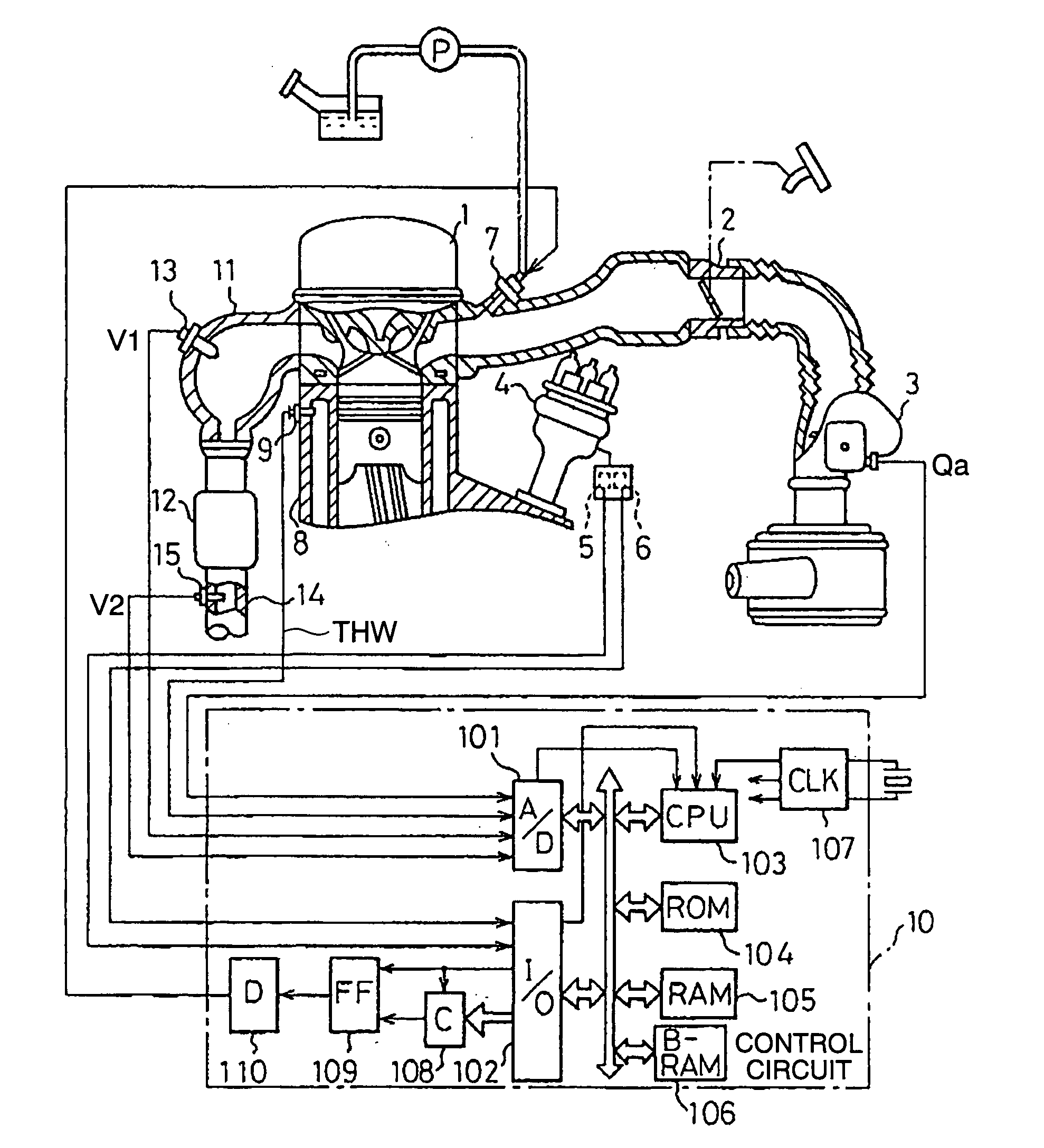
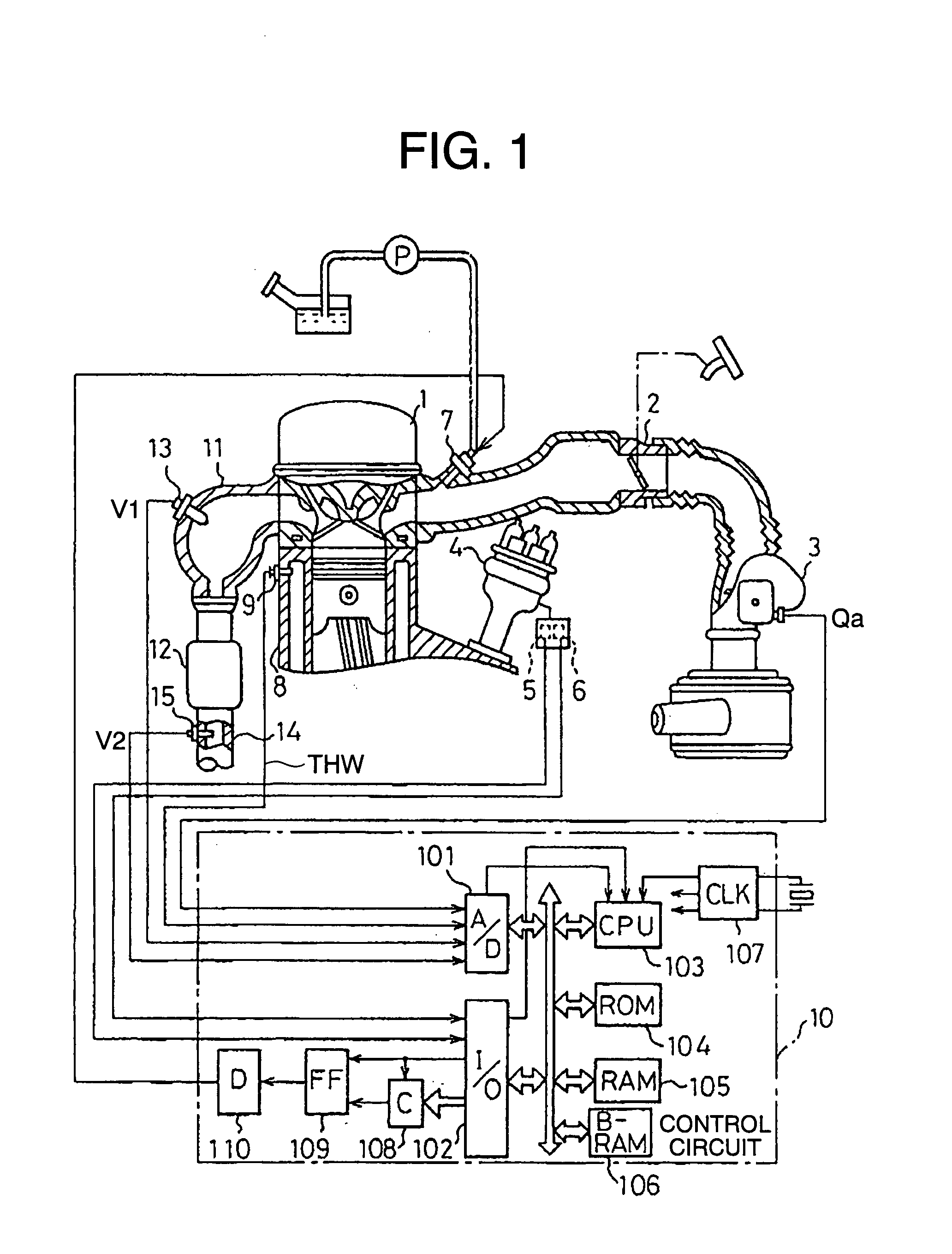
[0060]Now, referring to the drawings and first to FIG. 1, there is conceptually shown an air fuel ratio control apparatus for an internal combustion engine according to a first embodiment of the present invention. In FIG. 1, an air flow sensor 3 is arranged in an intake passage 2 of an engine proper 1 that constitutes an internal combustion engine (hereinafter also simply referred to as an engine). The air flow sensor 3 has a hot wire built therein for directly measuring an amount of intake air sucked into the engine proper 1, and generates an output signal (analog voltage) proportional to an amount of intake pg,15 air. The output signal of the air flow sensor 3 is supplied to the A / D converter 101 of the type having a built-in multiplexer in a control circuit 10 comprising a microcomputer.

[0061]A distributor 4 related to the ignition control of a plurality of cylinders is arranged in the engine proper 1, and has a pair of crank angle sensors 5, 6 arranged therein. One crank angle s...

embodiment 2

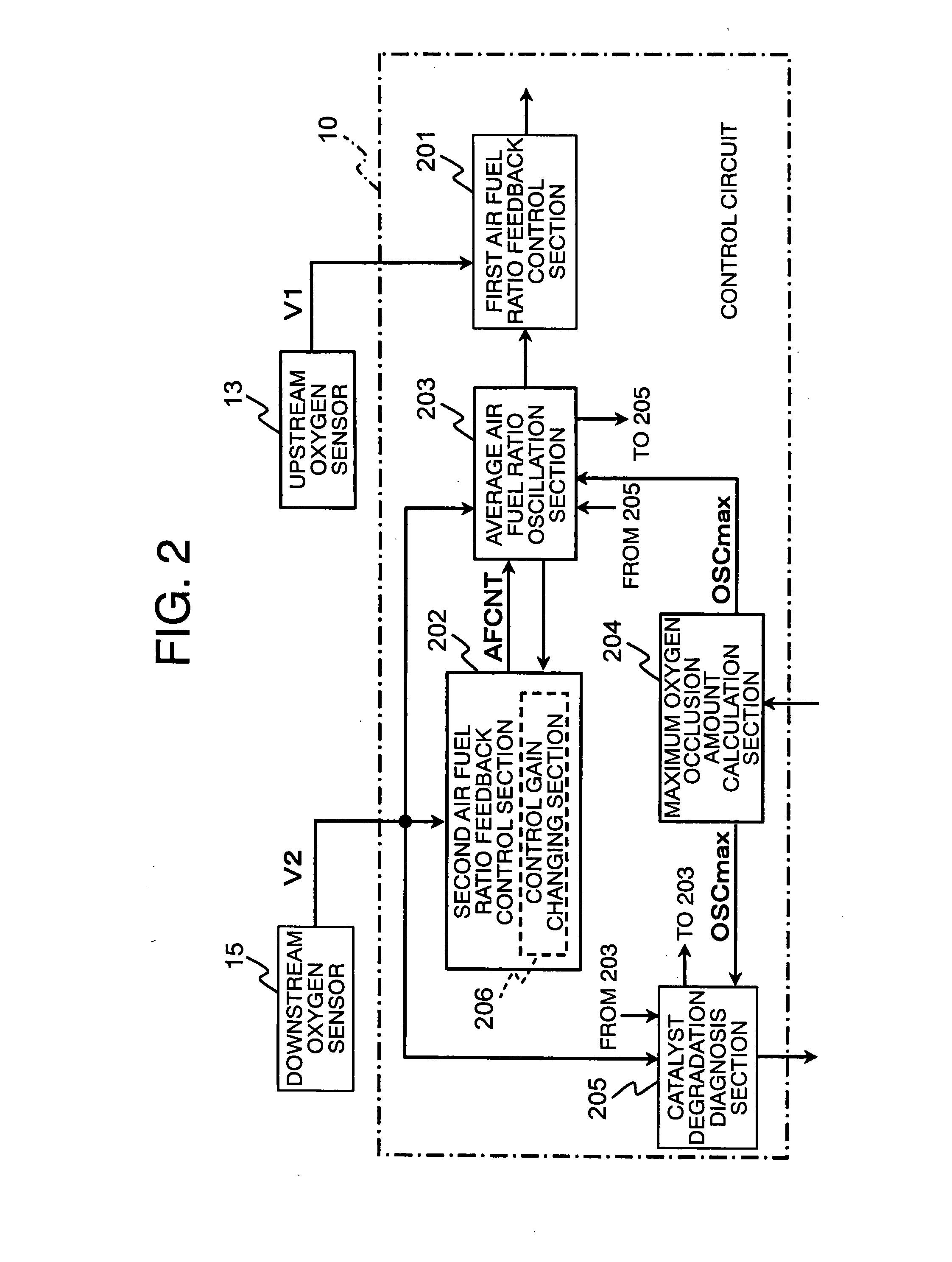
[0337]Although in the above-mentioned first embodiment, the average air fuel ratio oscillation section 203 executes oscillation processing based on the period counter Tmr, the oscillation processing may be executed based on an estimated value of the amount of oxygen occlusion (an estimated amount of oxygen occlusion OSC).

[0338]Hereinafter, reference will be made to a second embodiment of the present invention in which oscillation processing based on the estimated amount of oxygen occlusion OSC is executed, while referring to FIG. 28 through FIG. 31 together with FIG. 1 and FIG. 2. In this case, only a part of the calculation processing (see FIG. 6) according to the average air fuel ratio oscillation section 203 is different from that described in the above-mentioned first embodiment, but the overall construction and the other functions of the air fuel ratio control apparatus for an internal combustion engine according to this second embodiment are similar to those of the above-menti...


PUM


Abstract

An air fuel ratio control apparatus for an internal combustion engine can freely change an oscillation width of an amount of oxygen occlusion so as to adapt to or diagnose catalyst degradation without changing the settings of the period or width of the air fuel ratio oscillation. The apparatus includes a first air fuel ratio feedback control section that adjusts the air fuel ratio of a mixture supplied to an engine in accordance with an output value of an upstream air fuel ratio sensor and a predetermined control constant thereby to make the air fuel ratio periodically oscillate in rich and lean directions, and an average air fuel ratio oscillation section that operates the control constant based on an amount of oxygen occlusion of the catalyst so that an average air fuel ratio obtained by averaging the periodically oscillating air fuel ratio is caused to oscillate in the rich and lean directions.

Description

BACKGROUND OF THE INVENTION[0001]1. Field of the Invention[0002]The present invention relates to an air fuel ratio control apparatus for an internal combustion engine installed on a vehicle or the like. In particular, the invention relates to an air fuel ratio control apparatus for an internal combustion engine provided with an air fuel ratio feedback control section for oscillating the air fuel ratio of a mixture supplied to the internal combustion engine in rich and lean directions in a periodic manner.[0003]2. Description of the Related Art[0004]In general, a three-way catalyst (hereinafter referred to simply as a “catalyst”) for purifying harmful components HC, CO, NOx in an exhaust gas at the same time is installed in the exhaust passage of an internal combustion engine, and in this kind of catalyst, the purification rate of the harmful components HC, CO, NOx becomes high in the vicinity of the stoichiometric air fuel ratio. Accordingly, in air fuel ratio control apparatuses fo...

Claims


Application Information

Patent Timeline
IPC IPC(8): F01N3/00
CPCF01N3/10F01N11/007F02D41/22F02D41/1408F02D41/1441F02D41/0295
Inventor TAKUBO, HIDEKI
Owner MITSUBISHI ELECTRIC CORP
Features
  • Generate Ideas
  • Intellectual Property
  • Life Sciences
  • Materials
  • Tech Scout
  • Unparalleled Data Quality
  • Higher Quality Content
  • 60% Fewer Hallucinations
Learn More