
Turbine Static Structure for Reduced Leakage Air

a static structure and turbine technology, applied in the direction of machines/engines, stators, liquid fuel engines, etc., can solve the problems of large temperature gradients, high operating temperatures, high thermal and mechanical stresses, engine components, etc., and achieve the effect of reducing the amount of leakage air passing and reducing the stiffness of segments

Active Publication Date: 2008-06-26
H2 IP UK LTD
View PDF5 Cites 18 Cited by
  • Summary
  • Abstract
  • Description
  • Claims
  • Application Information

AI Technical Summary

Benefits of technology

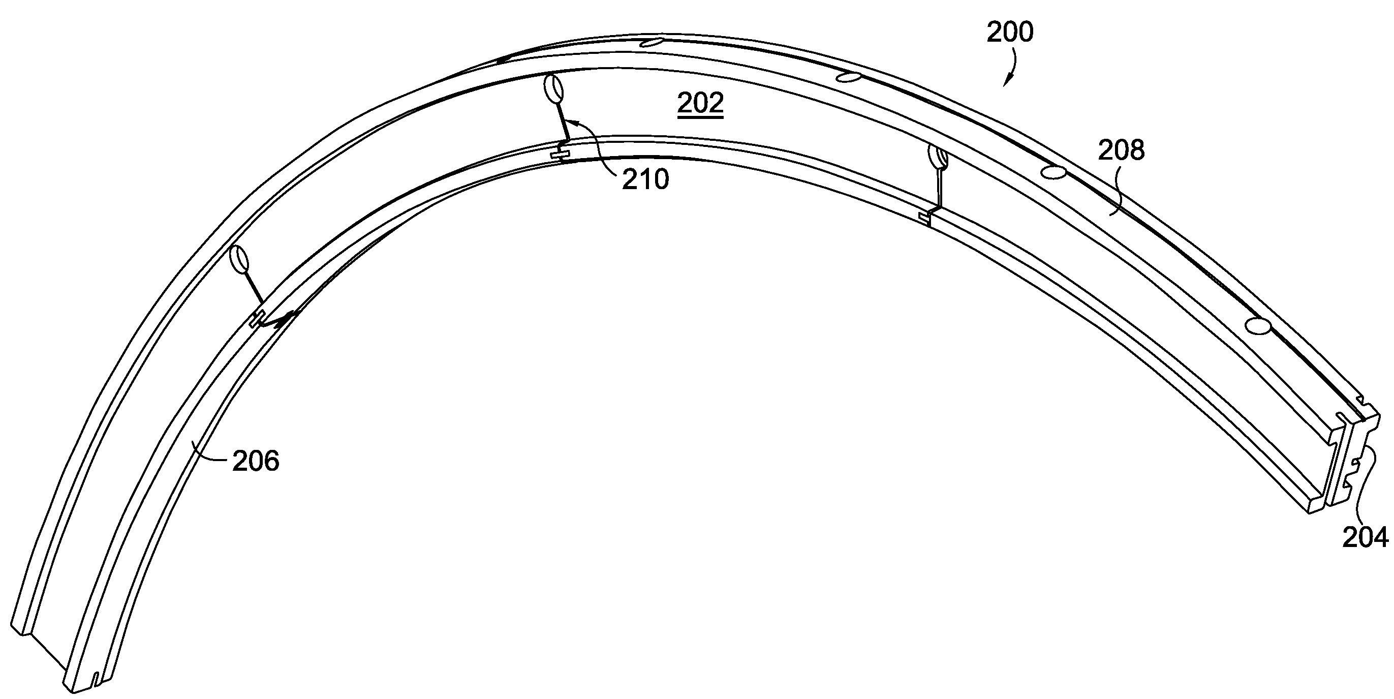
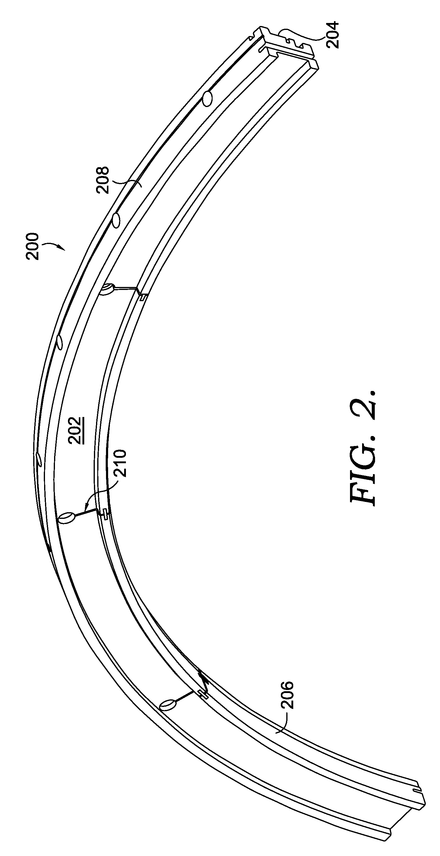
[0009]In an additional embodiment, a gas turbine engine is disclosed in which the engine includes one or more support ring structures proximate the turbine for supporting vane assemblies and shroud blocks. A support ring in accordance with this invention reduces the amount of leakage air passing there through by reducing the number of segments. A plurality of slots are provided in the larger ring segments to reduce stiffness of the segments. Each slot contains a seal member positioned to provide a seal against leakage of turbine cooling air.

Problems solved by technology

Gas turbine engines are known to operate in extreme environments exposing the engine components, especially those in the turbine section, to high operating temperatures as well as high thermal and mechanical stresses.
As a result of such elevated operating conditions, components in the turbine are exposed to large temperature gradients.
These temperature gradients can cause significant thermal growth in turbine components.
While active cooling, such as directing compressor discharge air through or across heated components, is an option, the more air taken from the compressor for cooling, the less efficient the engine, as less air is available for combustion and mechanical work.
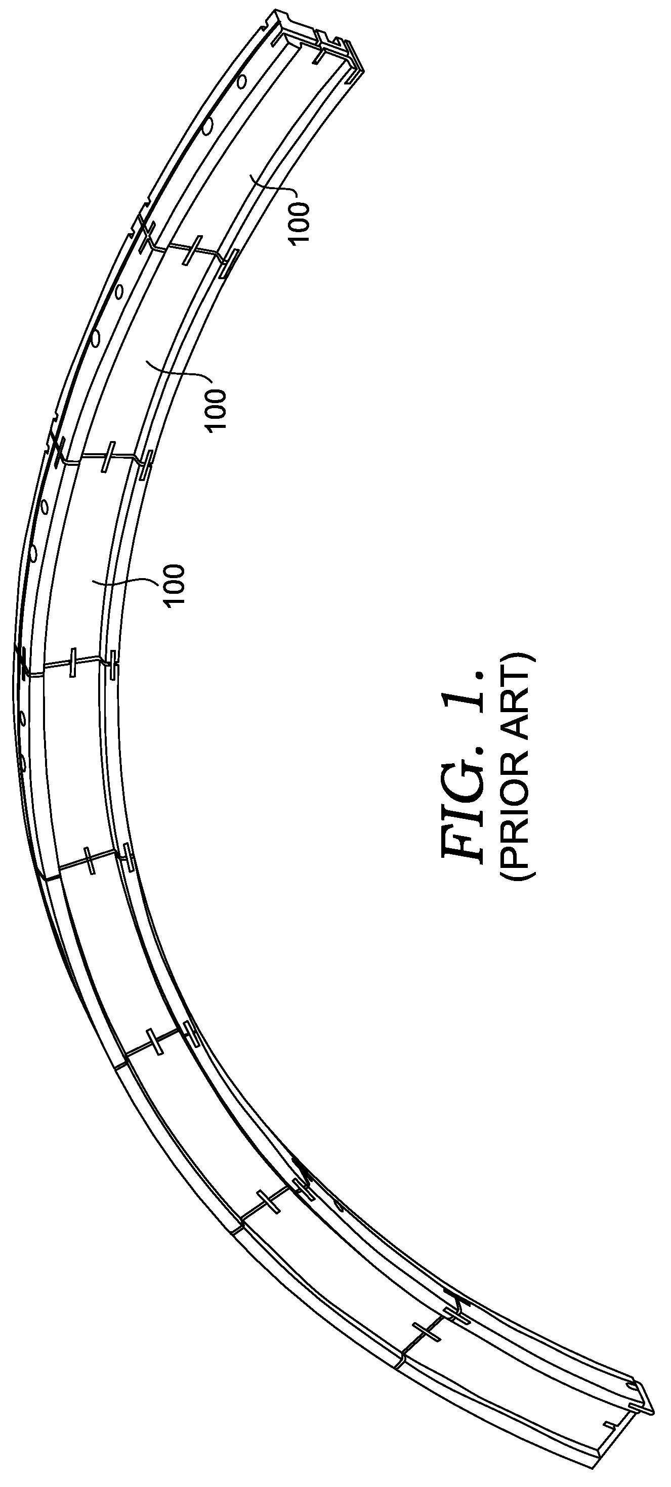
That means there are up to 48 gaps through which the air can leak if not properly sealed.
However, these gaps still leaked.
The leakage of cooling air results in reduced cooling air effectiveness, thereby requiring more air to cool the components.
As a result, that is less air to be directed through the combustor and turbine, thereby lowering efficiency of the turbine.
In addition to the leakage issues, assembling a ring with numerous segments (up to 48) and corresponding seals is a tedious and time-consuming process.

Method used


Image

  • Turbine Static Structure for Reduced Leakage Air
  • Turbine Static Structure for Reduced Leakage Air
  • Turbine Static Structure for Reduced Leakage Air

Examples


Embodiment Construction

[0022]The subject matter of the present invention is described with specificity herein to meet statutory requirements. However, the description itself is not intended to limit the scope of this patent. Rather, the inventors have contemplated that the claimed subject matter might also be embodied in other ways, to include different steps or combinations of steps similar to the ones described in this document, in conjunction with other present or future technologies. Moreover, although the terms “step” and / or “block” may be used herein to connote different elements of methods employed, the terms should not be interpreted as implying any particular order among or between various steps herein disclosed unless and except when the order of individual steps is explicitly described.

[0023]For clarity purposes, it is best to identify some of the common terminology that will be discussed in greater detail with respect to embodiments of the present invention. A “gas turbine engine,” as the term...


PUM


Abstract

A turbine static structure having reduced leakage air is disclosed. A static structure turbine support ring having few segments is disclosed in which the segments have improved thermal expansion capability with reduced air leakage. A plurality of radially extending slots are placed in the segments to reduce stiffness. In order to minimize air leakage through the support ring, generally circumferential slots are placed in the ring and connect with the generally radially extending slots. Positioned in each of the generally radially extending slots and generally circumferential slots, and in contact with each other, are two sheet metal plates. The plates are staked to the support ring structure so as to provide a seal member, yet compensate for thermal growth.

Description

CROSS-REFERENCE TO RELATED APPLICATIONS[0001]Not Applicable.STATEMENT REGARDING FEDERALLY SPONSORED RESEARCH OR DEVELOPMENT[0002]Not Applicable.TECHNICAL FIELD[0003]The present invention relates to gas turbines. More particularly, embodiments of the present invention relate to apparatus and method for reducing cooling air leakage through a turbine static structure.BACKGROUND OF THE INVENTION[0004]Gas turbine engines are known to operate in extreme environments exposing the engine components, especially those in the turbine section, to high operating temperatures as well as high thermal and mechanical stresses. As a result of such elevated operating conditions, components in the turbine are exposed to large temperature gradients. These temperature gradients can cause significant thermal growth in turbine components. As one skilled in the art will understand the amount of growth of an engine component is a function of the coefficient of thermal expansion for the material and the chang...

Claims


Application Information

Patent Timeline
IPC IPC(8): F02C7/20F01D11/00
CPCF01D11/08F05D2240/57F05D2240/11F01D25/246
Inventor ELLIS, CHARLIESTROHL, J. PAGETHOMAS, MATT
Owner H2 IP UK LTD
Learn More