Therapeutic arrangement

a technology of therapeutic arrangement and therapeutic device, which is applied in the direction of valve operating means/release devices, contraceptive devices, applications, etc., can solve the problems of complete failure of gas supply, user cannot estimate how long the ventilation apparatus is still operationally ready, etc., and achieve the effect of reducing power output, reducing energy, and prolonging the use time of the therapeutic arrangemen

Inactive Publication Date: 2008-06-26
DRAGERWERK AG
View PDF5 Cites 25 Cited by
  • Summary
  • Abstract
  • Description
  • Claims
  • Application Information

AI Technical Summary

Benefits of technology

[0008]The advantage of the invention is essentially that, with an impending exhaustion of the energy store, not only is a warning announcement outputted but the power output of the energy consumer is reduced in order to utilize the remaining energy supply over the longest possible time span. With a medical apparatus, functions necessary for life have the highest priority and are not permitted to be reduced whereas reductions are possible with respect to functions related to comfort.
[0009]According to a feature of the invention, the power input / power output of the energy consumer is adapted to the energy supply of the energy store. This adaptation can be so undertaken that the power input / power output is correspondingly tracked when there is a falling energy supply in order to achieve the longest possible use time of the therapeutic arrangement. The adaptation can be carried out proportionally to the decrease of the energy supply or can be undertaken based on a pregiven characteristic line. In the context of the invention, different characteristic lines can be held ready which, on the one hand, are adapted to the energy consumer and, on the other hand, contain settings specific to the user.
[0010]Heat sources in humidifiers or radiation heaters and mattress heaters in thermotherapeutic apparatus, for example, are energy consumers.
[0011]During in-hospital treatment in a medical treatment room, there is normally always a mains supply present in addition to an energy store. Accordingly, for example, the processor unit of a humidifier, which carries out the control of the heat source, makes routine inquiries as to the presence of a mains supply. The charging level of the energy store is continuously monitored with a charge level detector. If there is an interruption of the network power supply, then a switchover to the energy store takes place immediately and, depending upon the charge level of the energy store, an operating mode is selected by the processor unit with which the humidifier can be operated as long as possible.
[0012]In a first operating mode, it is provided by way of example that the full power output is available when there is a charge level of the energy store of greater than 75%. If the charge level lies between 50% and 75%, the power output of the heat source is reduced by 5% in a second operating mode. In a third operating mode, with a charge level between 10% and 50%, the power output is reduced by a further 10%. In contrast, if the charge level drops below 10% of the total capacity, the heating source is switched off.
[0013]It is advantageous when the user can himself or herself change the settings for reducing the energy. Accordingly, the user could impart to the system that a switchover into an operating mode should not take place because the user is sure that the interruption of the power source will not exceed a certain time duration. On the other hand, the user could just as well select, ab initio, the operating mode having the greatest energy savings because the power source will not be available for a presumably long time. One could also, in addition, conceive of a selection from differently structured profiles. One of these profiles is the simple power reduction corresponding to predetermined operating modes. A further profile could be directed to a maximum patient comfort; however, then a shorter running time is to be expected since the energy store is exhausted fastest. In this case, the power of the system would not be reduced or reduced only very slightly. An alternative profile could be designed for maximum running time without mains supply. In this case, reductions as to comfort for the patient are to be made because this results in a very substantial reduction of the capacity of the systems. In addition, it is conceivable that a certain number of additional profiles is provided which can be freely configured by the user.

Problems solved by technology

The disadvantage of the known arrangement is that only the remaining residual capacity of the battery is indicated and the user can only estimate how long the ventilation apparatus is still operationally ready.
If no power mains is available, then a complete failure of the gas supply occurs when the battery is completely exhausted.

Method used


Image

  • Therapeutic arrangement
  • Therapeutic arrangement
  • Therapeutic arrangement

Examples


Embodiment Construction

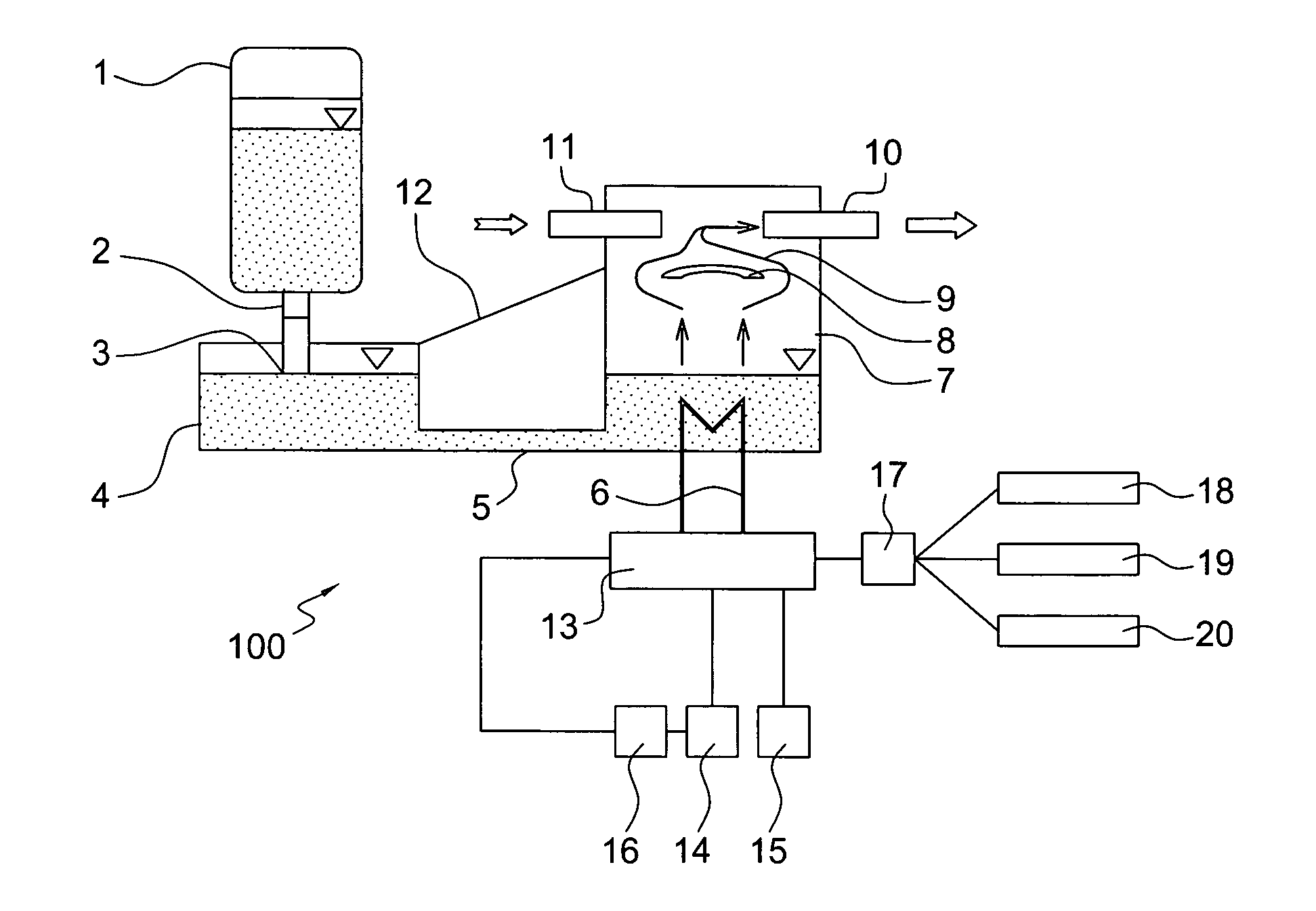
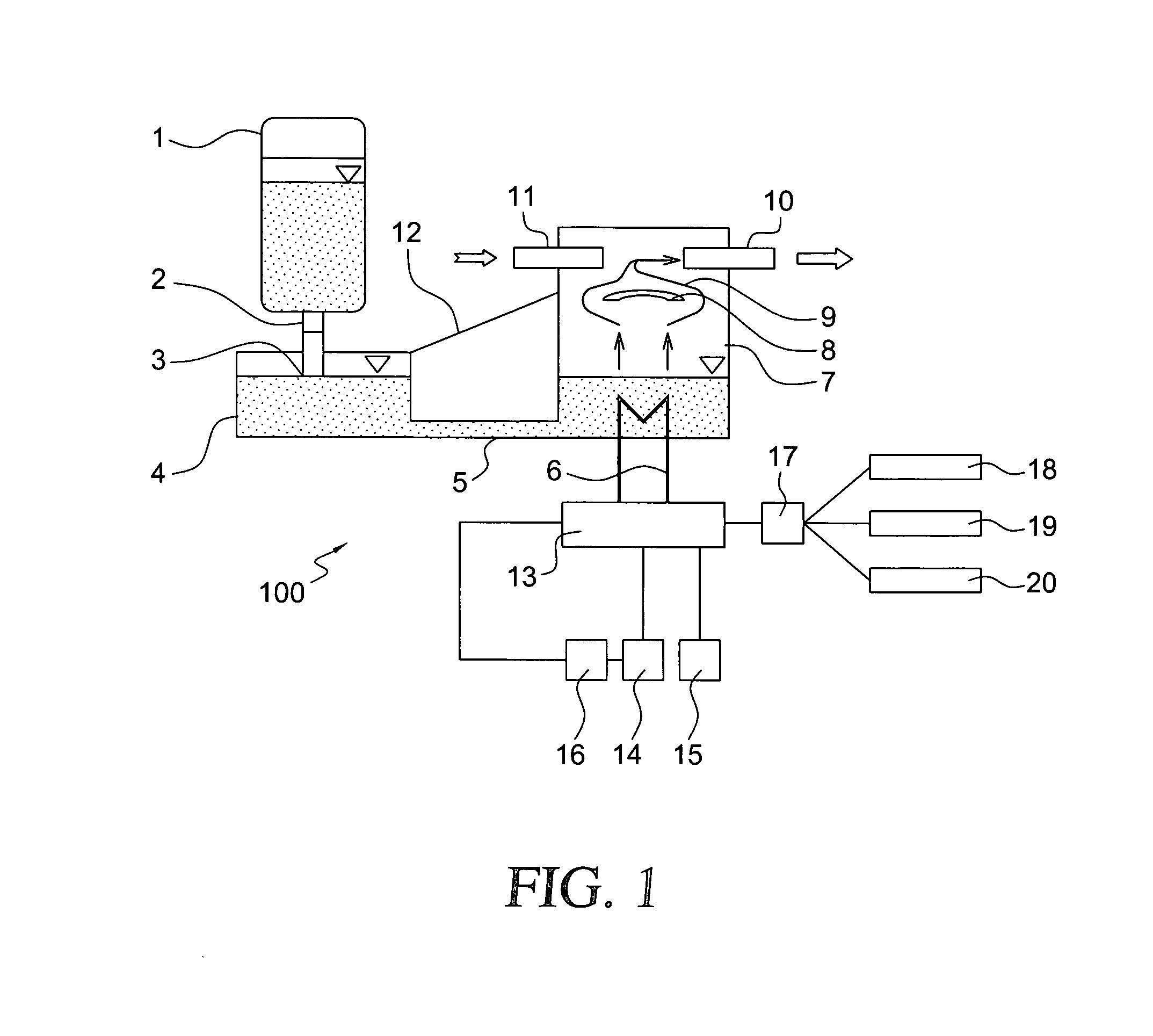
[0028]FIG. 1 shows the configuration of a humidifier 100 for breathing gas. Sterile water is held ready in an exchangeable, pressure-stable closed water supply vessel 1. The water supply vessel 1 is connected to an intermediate store 4 via a connector 2. In this way, water can run out of the water supply vessel 1 into the intermediate store 4 of the humidifier system until the water level has risen so far that the channel 3 of the connector 2 is closed and no air can any longer flow into the water supply vessel 1. The water is conducted into the vaporizer chamber 7 via a water connecting line 5 having a diameter of approximately 1 to 2.5 millimeters.

[0029]In the vaporizer chamber 7, the heater 6 ensures the necessary energy to heat up the water and to cause the water to boil and vaporize. The water vapor rises in the vaporizer chamber 7 and is redirected by a shield 8 so that water vapor reaches the inhalation gas. The water vapor is conducted along the path 9 into the outlet 10 and...


PUM


Abstract

A therapeutic apparatus for medical applications is improved in such a manner that the capacity of an energy store can be utilized as best as possible when there is a breakdown of the power supply. A charge level detector (16) is provided for the energy store which reduces the power output of the energy consumer (6) when there is a falling charge level of the energy store (14) with a drop of the supply voltage (15).

Description

CROSS REFERENCE TO RELATED APPLICATION[0001]This application claims priority of German patent application no. 10 2006 059 340.5, filed Dec. 15, 2006, the entire content of which is incorporated herein by reference.FIELD OF THE INVENTION[0002]The invention relates to a therapeutic arrangement for applications in medicine.BACKGROUND OF THE INVENTION[0003]U.S. Pat. No. 5,950,621 discloses a ventilating apparatus wherein ambient air is drawn by suction through a filter by means of a pump unit and is supplied to a patient with a breathing mask. The pump unit comprises a blower which is connected to a battery via a data collection unit.[0004]The data collection unit monitors the voltage of the battery and warns the user of impending battery failure via optical and acoustic alarm devices. The alarm indication can be outputted as a simple signal or as a complex warning sequence. In addition, blinking lights, intensity modulations or color changes can be used in order to indicate different s...

Claims


Application Information

Patent Timeline
Patent Type & Authority Applications(United States)
IPC IPC(8): A61M16/10A62B7/00A62B9/00
CPCA61B2560/0209A61F7/007A61F2007/0078A61M5/142A61M16/109A61M16/16A61M16/162A61M2205/8212A61N5/06A61M16/1075A61M16/021
Inventor BECKER, UWEKOCH, JOCHIMLORENZ, BERNHARD
Owner DRAGERWERK AG
Why Eureka
Try Eureka