Magnetic friction clutch

a friction clutch and magnetic technology, applied in the direction of friction clutches, clutches, non-mechanical actuated clutches, etc., to achieve the effect of reducing the magnetic scatter flux, good magnetic permeance of the second clutch part, and great mechanical stability

Inactive Publication Date: 2008-06-26
SCHAEFFLER TECH AG & CO KG
View PDF5 Cites 4 Cited by
  • Summary
  • Abstract
  • Description
  • Claims
  • Application Information

AI Technical Summary

Benefits of technology

[0004]An object of the present invention is to provide a magnetic friction clutch of the type named at the beginning, which is economical to produce and enables highly dynamic adjustments. In addition, the friction clutch should enable high torque transfer relative to the construction space required for the second clutch part.

Problems solved by technology

However, the requirements for mechanical stability of the second clutch part permit only a relatively small number of flux conducting rings.

Method used


Image

  • Magnetic friction clutch
  • Magnetic friction clutch
  • Magnetic friction clutch

Examples


Embodiment Construction

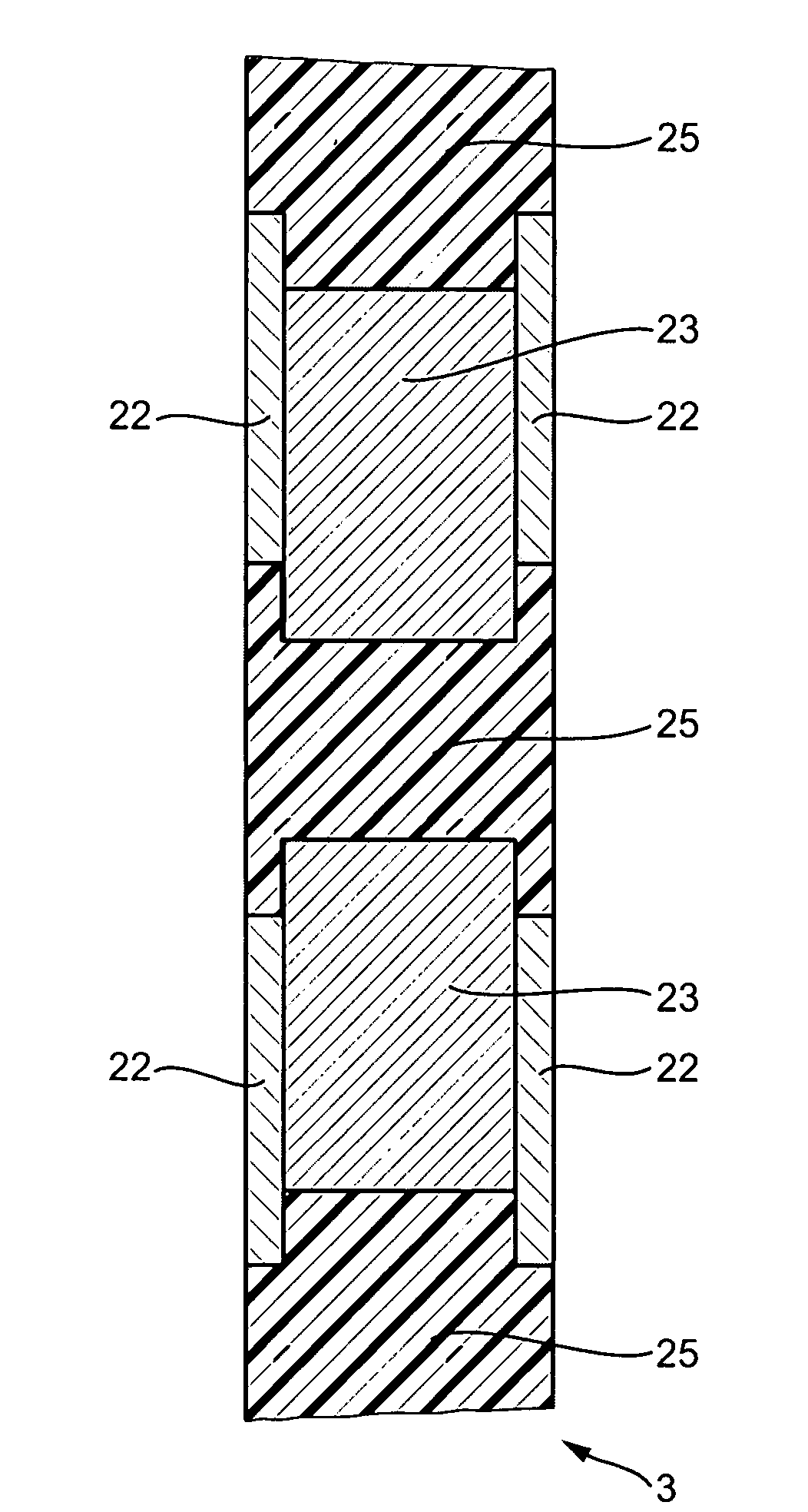
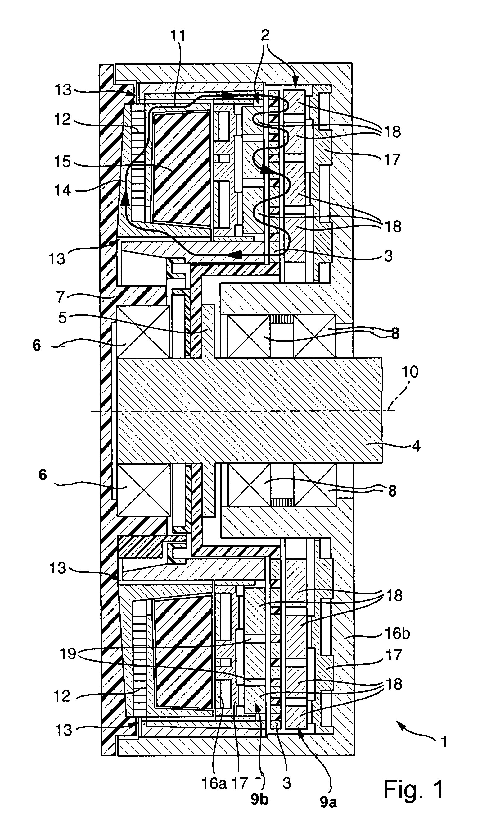
[0028]A magnetic friction clutch designated in the aggregate as 1 has a first clutch part 2 and a second clutch part 3 which is rotatably mounted relative thereto, which are situated on a shaft 4 that may be for example the camshaft of a combustion engine. In FIG. 1 it can be seen that the second clutch part 3 is connected to the shaft 4 at a flange 5 provided on the shaft 4. The first clutch part 2 is connected to the shaft 4 through a first roller bearing 6 situated on the shaft 4, so that it can rotate around the longitudinal central axis of the shaft 4. Also situated on the shaft 4 is a second roller bearing 8, through which the shaft 4 is rotatably supported on a stator flange 7.

[0029]The first clutch part 2 has two clamping jaws 9a, 9b, which are movable toward and away from each other by a few micrometers axially to the shaft 4. An outer clamping jaw 9a is of ring-shaped design and has an approximately U-shaped ring cross section in a diametrical plane spanning through the ax...


PUM


Abstract

A magnetic friction clutch has two clutch parts, supported so that they can rotate relative to each other around an axis of rotation. A first clutch part has at least two clamping jaws which are movable somewhat toward and away from each other. A second clutch part, situated between the clamping jaws, is of disk-shaped design. The clamping jaws are pressable against the second clutch part by the magnetic force of a variable magnetic flux which is carried in the clutch parts in a soft magnetic material, in order to form a frictionally engaged connection between the clutch parts. The second clutch part has a plurality of soft magnetic ring zones permeated by the magnetic flux, which extend in the circumferential direction and are separated from each other in the radial direction by slots running in the circumferential direction. Ring zones adjacent to each other in the radial direction are connected with each other by bridging links. The slots are filled with a solidified casting material that connects the ring zones with each other. Inner and / or outer circumferential surfaces of the ring zones that face each other follow a line that deviates from a circular line running concentric to the axis of rotation. The second clutch part can have a plurality of layers made of different soft magnetic materials.

Description

[0001]This application is a continuation of prior International Application PCT / DE2006 / 000774, filed on May 4, 2006, which is hereby incorporated by reference herein.BACKGROUND[0002]The invention relates to a magnetic friction clutch, having at least two clutch parts supported so that they are rotatable relative to each other around an axis of rotation, where a first clutch part has at least two clamping jaws that are movable somewhat toward each other and away from each other, where a second clutch part situated between the clamping jaws is disk-shaped, where the clamping jaws may be pressed against the second clutch part by the magnetic force of a variable magnetic flux which is carried in the clutch parts in a soft magnetic material in order to form a frictionally engaged connection between the clutch parts, where the second clutch part has a plurality of soft magnetic ring zones permeated by the magnetic flux, which extend in the circumferential direction and are separated from ...

Claims


Application Information

Patent Timeline
Patent Type & Authority Applications(United States)
IPC IPC(8): F16D27/112F16D27/14
CPCF16D27/112F16D2027/008F16D27/14
Inventor HILL, WOLFGANG
Owner SCHAEFFLER TECH AG & CO KG
Why Eureka
Try Eureka