Modular unmanned air-vehicle

Inactive Publication Date: 2008-06-26
COLGREN RICHARD D +2
View PDF16 Cites 65 Cited by
  • Summary
  • Abstract
  • Description
  • Claims
  • Application Information

AI Technical Summary

Benefits of technology

[0008]The aircraft can be designed so that it can be disassembled into several small pieces or modular components, which provides several advantages. First, the modular design makes transporting the aircraft much easier because it can be disassembled into its modular components for ease of stowing and transporting. Second, if the aircraft incurs any local damage to one or more of the modular components, the damaged part can simply be replaced rather than repaired. This decreases the life-cycle cost of the aircraft, as repairing fiberglass can be a difficult and costly process. Lastly, this can allow the user to fly the aircraft with all four wing sections (the long wing configuration) or with just two wing sections (the short wing configuration). This makes the aircraft usable for missions requiring short takeoff and landing and high endurance (long wing), or missions requiring higher speed and range (short wing). No other UAV (or other aircraft) has this unique feature.
[0009]Another novel aspect of the present invention is the wing

Problems solved by technology

Second, if the aircraft incurs any local damage to one or more of the modular components, the damaged part can simply be replaced ra

Method used


Image

  • Modular unmanned air-vehicle
  • Modular unmanned air-vehicle
  • Modular unmanned air-vehicle

Examples


Example

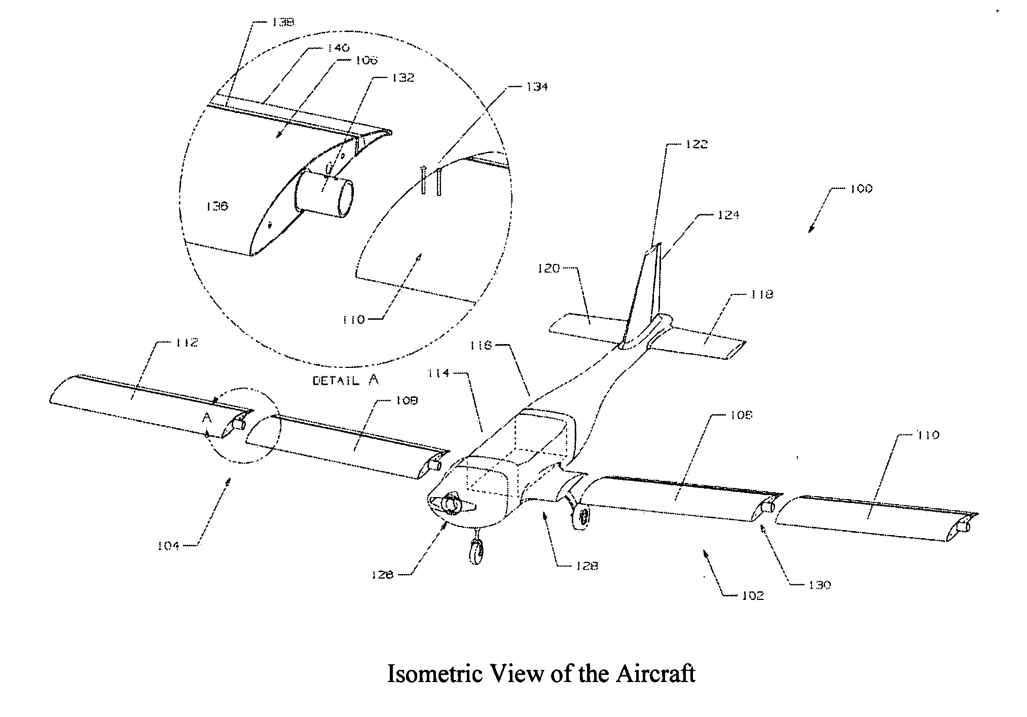
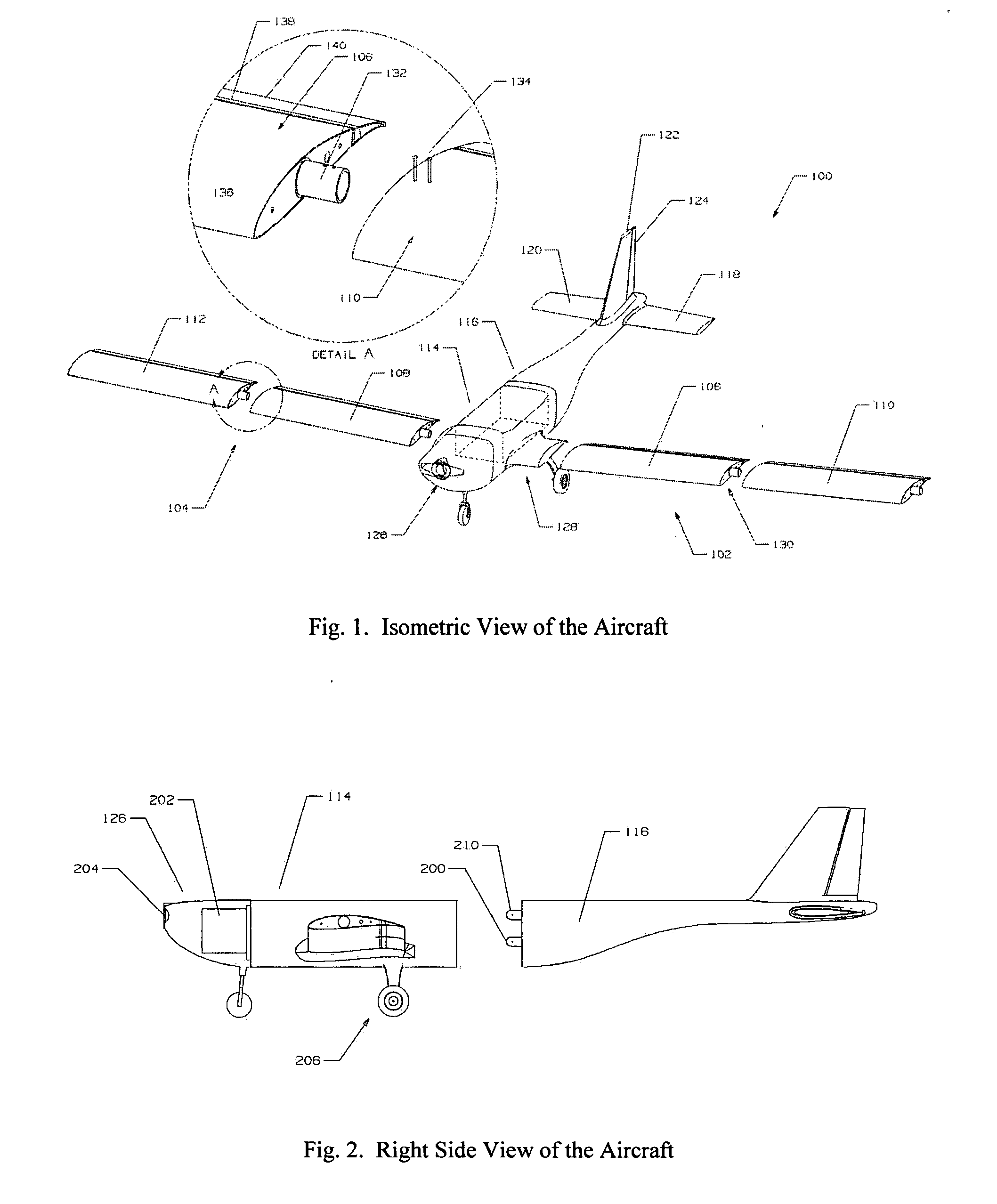
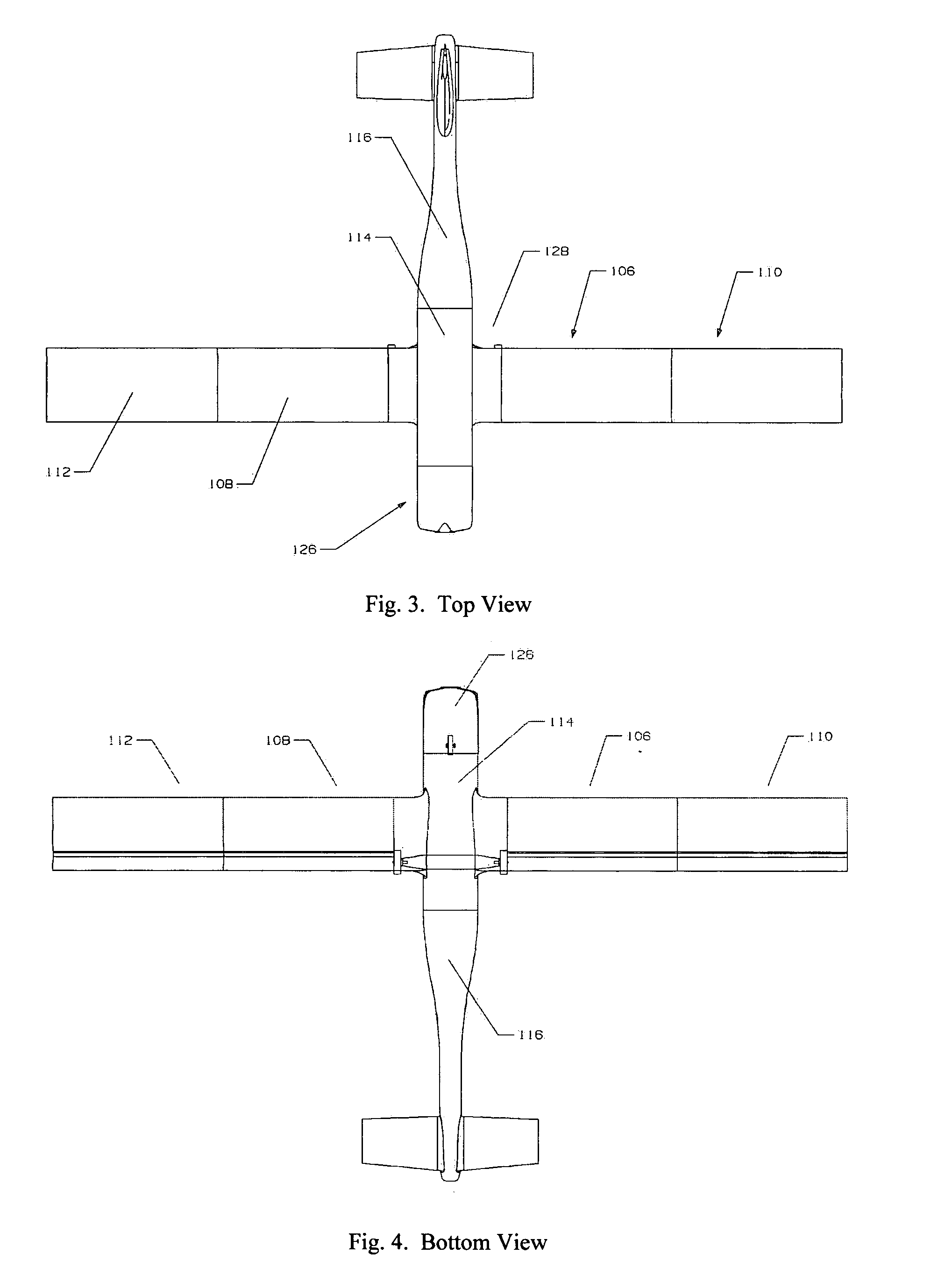
[0021]According to the embodiment(s) of the present invention, various views are illustrated in FIG. 1-5 and like reference numerals are being used consistently throughout to refer to like and corresponding parts of the invention for all of the various views and figures of the drawing. Also, please note that the first digit(s) of the reference number for a given item or part of the invention should correspond to the FIG. number in which the item or part is first identified.

[0022]One embodiment of the present invention comprising a monoplane airframe including various modular components including modular wing sections and forward and aft fuselage sections figures a novel apparatus for a modular unmanned vehicle.

[0023]The details of the invention and various embodiments can be better understood by referring to the figures of the drawing. Referring to FIG. 1, a partially exploded isometric view of an unmanned air vehicle is shown. The modular structure of the airframe is illustrated by...


PUM


Abstract

An unmanned air vehicle designed for reconnaissance, surveillance, data acquisition, and general research. The vehicle is a monoplane that is comprised of several pieces that can easily be assembled using a minimal amount of tools. The aircraft consists of a forward and aft fuselage section, two identical horizontal stabilizers, and four identical wing sections. The aircraft can fly with all four wing sections, or with just two wing sections (the short wing configuration). This makes the aircraft usable for missions requiring short takeoff and landing and high endurance (long wing), or missions requiring higher speed and range (short wing). No other UAV (or other aircraft) has this unique feature. Another novel aspect of the present invention is the wing control can be specially designed to increase the effectiveness of the wing control surface while minimizing the effect the control surface has on the overall aerodynamics of the wing, namely drag.

Description

BACKGROUND OF INVENTION[0001]1. Field of Invention[0002]This invention relates generally to unmanned air vehicles (UAVs) and, more particularly, to engine powered unmanned air vehicles.[0003]2. Background Art[0004]Unmanned air vehicles are utilized to perform various tasks such as, for example, reconnaissance and surveillance, data acquisition, and general research such as the study of weather patterns. Unmanned air vehicles can take on various forms from gas filled inflatables such as helium balloons, to gliders, to engine powered aircraft. Engine powered aircraft certainly have their advantages in that they can typically fly over and cover long ranges more quickly, fly at higher altitudes, carry heavier payloads to higher altitudes and over longer distances, can typically be controlled with greater agility over a larger flight envelope, and can typically be designed with more versatile all-weather capability.[0005]However, engine powered unmanned air vehicles have their shortcomin...

Claims


Application Information

Patent Timeline
IPC IPC(8): B64C3/38B64C1/26
CPCB64C9/02B64C2201/021B64C39/024B64C2211/00B64U10/25
Inventor COLGREN, RICHARD D.HOLLY, LANCE C.DONOVAN, WILLIAM R.
Owner COLGREN RICHARD D
Why Eureka
Try Eureka