Light-emitting apparatus and method of producing the same

a technology of light-emitting apparatus and light-emitting light, which is applied in the direction of electrical apparatus, semiconductor/solid-state device manufacturing, semiconductor devices, etc., can solve the problems of large color non-uniformity, large and parts of the apparatus are deteriorated or failed, so as to improve the light extraction efficiency and small color irregularity in the outputted light

Active Publication Date: 2008-06-26
NICHIA CORP
View PDF15 Cites 125 Cited by
  • Summary
  • Abstract
  • Description
  • Claims
  • Application Information

AI Technical Summary

Benefits of technology

[0012]It is an object of the present invention to provide a light-emitting apparatus having an improved light extraction efficiency, and small color irregularity in the outputted light even if a light-emitting device is mounted offset from the desired position, and a method of producing the same.

Problems solved by technology

Further, if the distance from the lower edge of the LED chip to the inner surface of the side wall portion is made large, color irregularity in the outputted light becomes large when the LED chip is mounted at a position offset from the predetermined position.
In other words, when the LED chip is mounted at a position offset from the predetermined position, the amount of the phosphor material around the LED chip becomes uneven, leading to different conversion amount of the light emitted from the light-emitting device according to location, resulting in large color non-uniformity.
On the other hand, when the light-emitting apparatus is mounted on a circuit board at a high density, the parts of the apparatus is deteriorated or failed due to the heat generated when the light-emitting device emits light.

Method used


Image

  • Light-emitting apparatus and method of producing the same
  • Light-emitting apparatus and method of producing the same
  • Light-emitting apparatus and method of producing the same

Examples


first embodiment

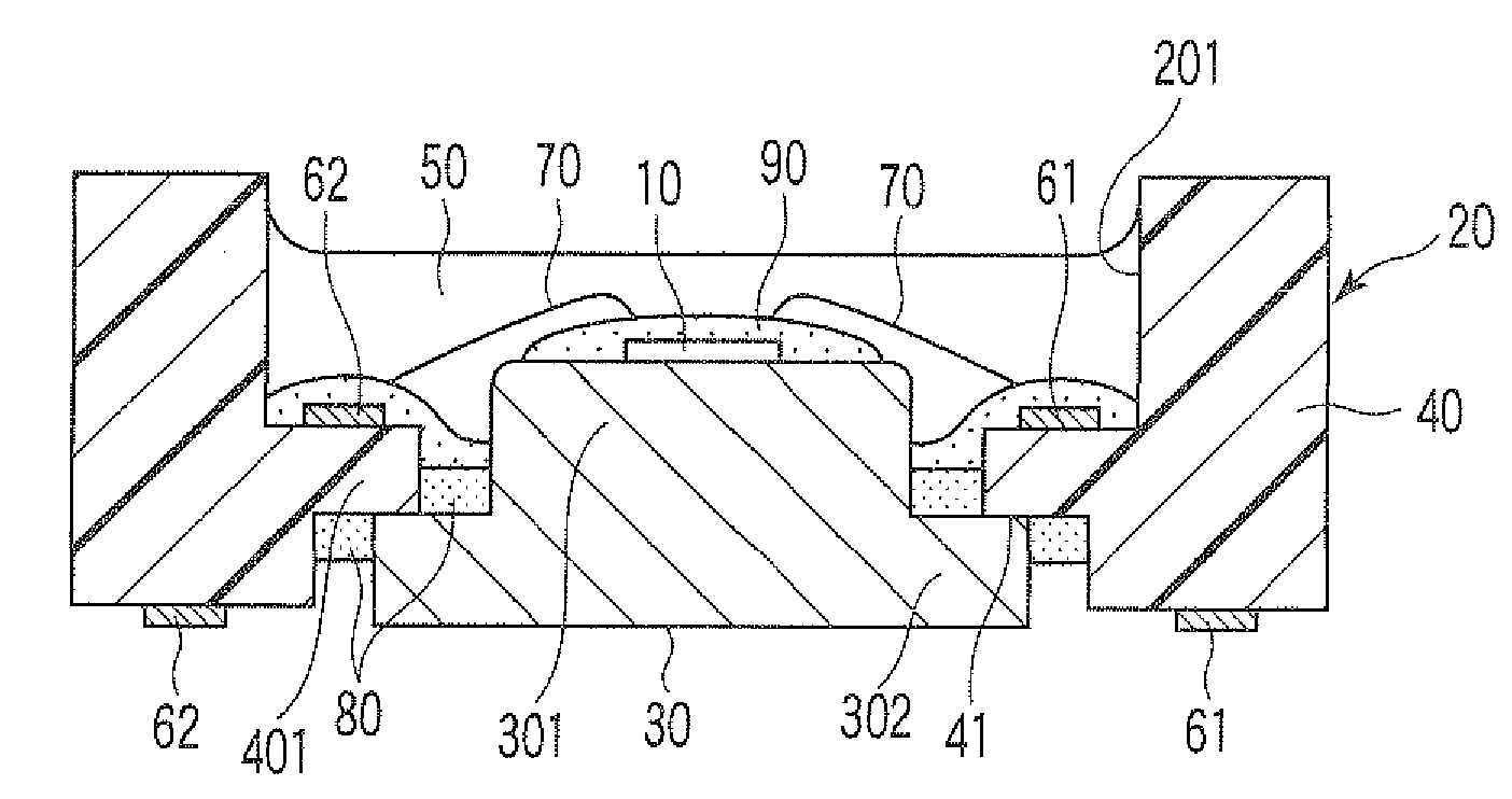
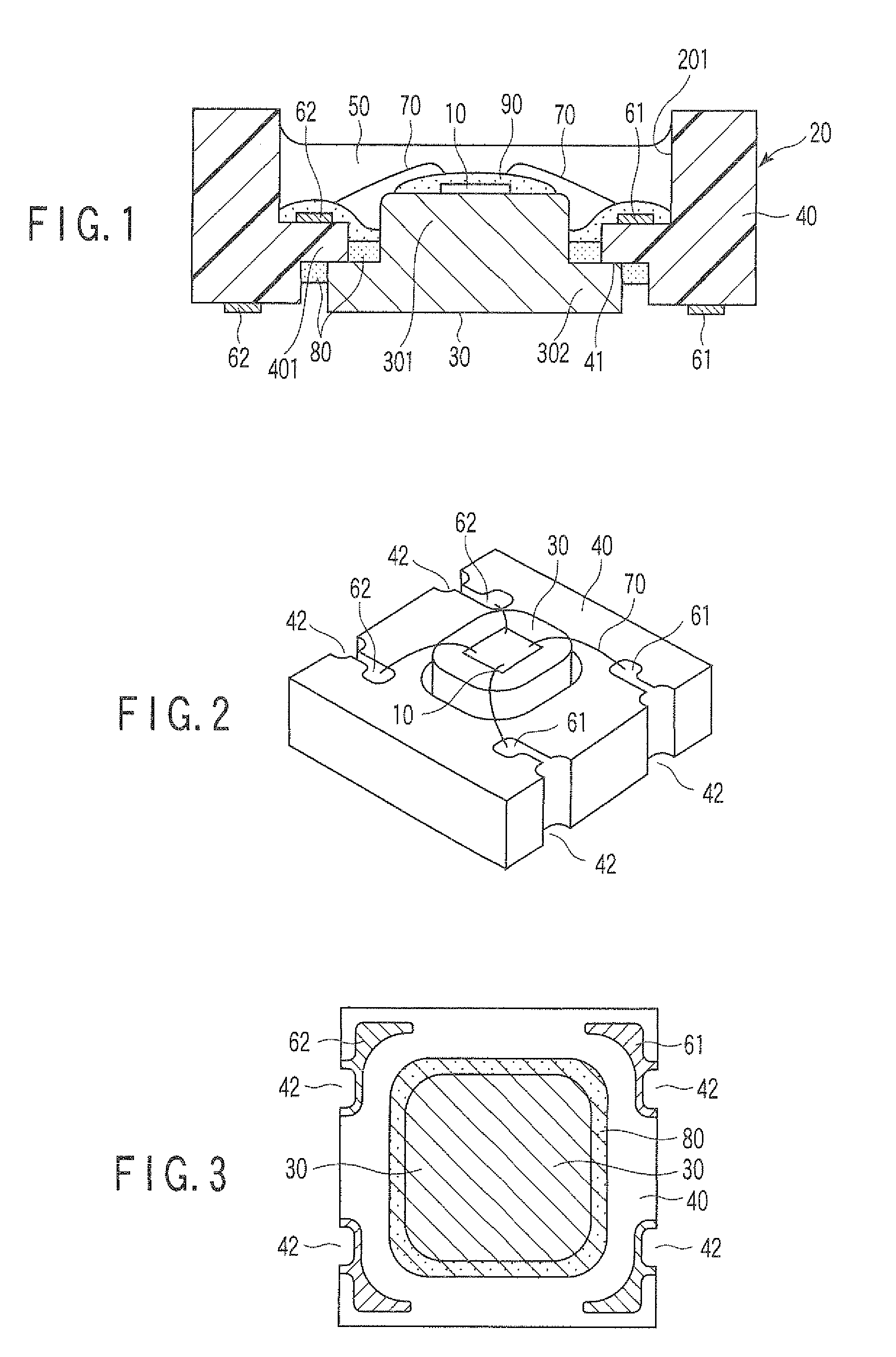
[0034]FIG. 1 is a side sectional view schematically illustrating a light-emitting apparatus according to a first embodiment of the present invention. FIG. 2 is an oblique view of the apparatus of FIG. 1 with a cup of the package, a color conversion layer and a light-transmitting member omitted. FIG. 3 is a back side view showing a lower bottom surface of the light-emitting apparatus of FIG. 1. FIG. 4 is an enlarged view schematically illustrating the distribution of the color conversion layer on the bottom of the cup, including the pedestal, of FIG. 1.

[0035]A light-emitting apparatus 10 illustrated in FIGS. 1 to 4 comprises a package 20 which includes a support 30 having a central section 301 and a peripheral section 302 around the central section 301. The support 30 provides a bottom of the package 20. A side wall 40 surrounds the bottom 30 to define a cup 201 together with the bottom. The central section 301 is raised upwardly higher than the peripheral section 302, providing a pe...

second embodiment

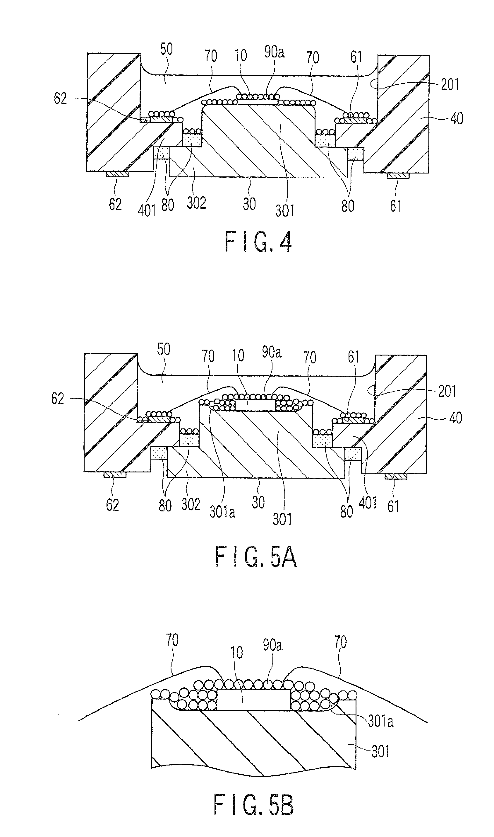
[0080]FIG. 5A is a side sectional view schematically illustrating a light-emitting apparatus according to a second embodiment of the present invention, and FIG. 5B is an enlarged view partially illustrating the pedestal on which the light-emitting device is mounted, with a color conversion layer covering the upper surface of the pedestal, including the surface of the light-emitting device. The light-emitting apparatus illustrated in FIGS. 5A and 5B is of the same construction as the construction of the apparatus according to the first embodiment, except that the central region of the upper surface of the pedestal 301 is recessed. The light-emitting device 10 is placed in the recess 301a. In this case, the phosphor particles 90a can be deposited thicker on the bottom surface of the recess 301a than on the upper surface of the light-emitting device 10. In other words, the phosphor particles 90a can be deposited to cover the entire side surfaces of the light-emitting device 10 in the r...

third embodiment

[0083]FIG. 6 is a side sectional view schematically illustrating a light-emitting apparatus according to a third embodiment of the present invention. The light-emitting apparatus according to the third embodiment is of the same construction as the construction of the apparatus according to the first embodiment, except that a die bonding member 100 securing the LED chip 10 on the pedestal 301 covers that region of the side surface of the LED chip 10 which corresponds to half to less than the height of the side surface of the LED chip 10. For example, a resin fillet surface is formed on the side surface of the LED chip 10.

[0084]The position of the light-emitting layer of the LED chip 10 varies dependent on the kind of the LED chip. However, in usual LED chips, the light-emitting layer is exposed at the side surface of the LED chip at a position half or more the height of the side surface of the LED chip. In this embodiment, the die bonding member 100 extends from the lower edge of the...


PUM


Abstract

A light-emitting apparatus includes a package including a support having a central section and a peripheral section around the central section. The central section is raised upwardly from the peripheral section, providing a pedestal for supporting a light-emitting device. A light-emitting device secured on an upper surface of the pedestal and has electrodes. Electrically conductive members are provided on a peripheral region of the package and electrically connected to the electrodes of the light-emitting device. A color conversion layer covers the light-emitting device. A light-transmitting member is formed in the package, sealing at least the light-emitting device together with the color conversion layer. The pedestal has its side surface at least partially exposed from the color conversion layer.

Description

CROSS-REFERENCE TO RELATED APPLICATIONS[0001]This application is based upon and claims the benefit of priority from prior Japanese Patent Applications No. 2006-350079, filed Dec. 26, 2006; No. 2007-050109, filed Feb. 28, 2007; and No. 2007-244433, filed Sep. 20, 2007, the entire contents of all of which are Incorporated herein by reference.BACKGROUND OF THE INVENTION[0002]1. Field of the Invention[0003]The present invention relates to a light-emitting apparatus and a method of producing the same, and more particularly, to a light-emitting apparatus in which an outputted light of a light-emitting device is converted in wavelength by a color conversion layer, and a method of producing the same.[0004]2. Description of the Related Art[0005]Conventionally, a light-emitting apparatus is known which comprises a package having a bottom and a side wall portion surrounding the bottom so as to define a cup with the bottom. A light-emitting device is contained in the cup, and a light-transmitti...

Claims


Application Information

Patent Timeline
Patent Type & Authority Applications(United States)
IPC IPC(8): H01L33/00H01L33/48H01L33/50H01L33/64
CPCH01L33/486H01L33/505H01L33/642H01L2224/32188H01L2924/01079H01L2924/01322H01L2224/48091H01L2924/3025H01L2224/8592H01L2924/00014H01L2924/00H01L2924/181H01L2924/00012
Inventor AMO, TAKAHIRONISHIJIMA, SHINJIOKADA, SATOSHIHODONO, YOSHIFUMI
Owner NICHIA CORP
Why Eureka
Try Eureka