Imaging Cartridge Drive Having Entire Tooth Engagement

a technology of cartridge drive and tooth engagement, which is applied in the direction of instruments, electrographic process equipment, optics, etc., can solve the problem of rendering the cartridge apparatus inoperabl

Inactive Publication Date: 2008-06-26
MILLER STEVEN
View PDF1 Cites 2 Cited by
  • Summary
  • Abstract
  • Description
  • Claims
  • Application Information

AI Technical Summary

Benefits of technology

[0005]The long-standing but heretofore unfulfilled need for a toner cartridge that is adapted to be of an simplified construction, thereby limiting the number of elements required during manufacture, and which also includes improvements that overcome the limitations of prior art toner cartridges is now met by a new, useful, and non-obvious invention.
[0009]The hopper pin horizontal retainer has an upwardly inclined surface, a concavity, and a hump between the upwardly inclined surface and the concavity. The hopper pin engages the upwardly inclined surface and causes the hopper pin horizontal retainer to momentarily deflect from its position of repose when the waste bin is lowered with respect to the hopper. When the hopper pin rolls over the hump the resiliency of the hopper pin horizontal retainer causes the hopper pin horizontal retainer to return to its position of repose, thereby capturing the hopper pin in the concavity.

Problems solved by technology

Such dynamic biasing means disposed between the respective elements are prone to failure, rendering the cartridge apparatus inoperable.

Method used


Image

  • Imaging Cartridge Drive Having Entire Tooth Engagement
  • Imaging Cartridge Drive Having Entire Tooth Engagement
  • Imaging Cartridge Drive Having Entire Tooth Engagement

Examples


first embodiment

[0069]the novel latching means for interconnecting waste bin 2 and hopper 3 to one another without the use of a dynamic biasing element is best illustrated in FIGS. 5A-B and 6A-B.

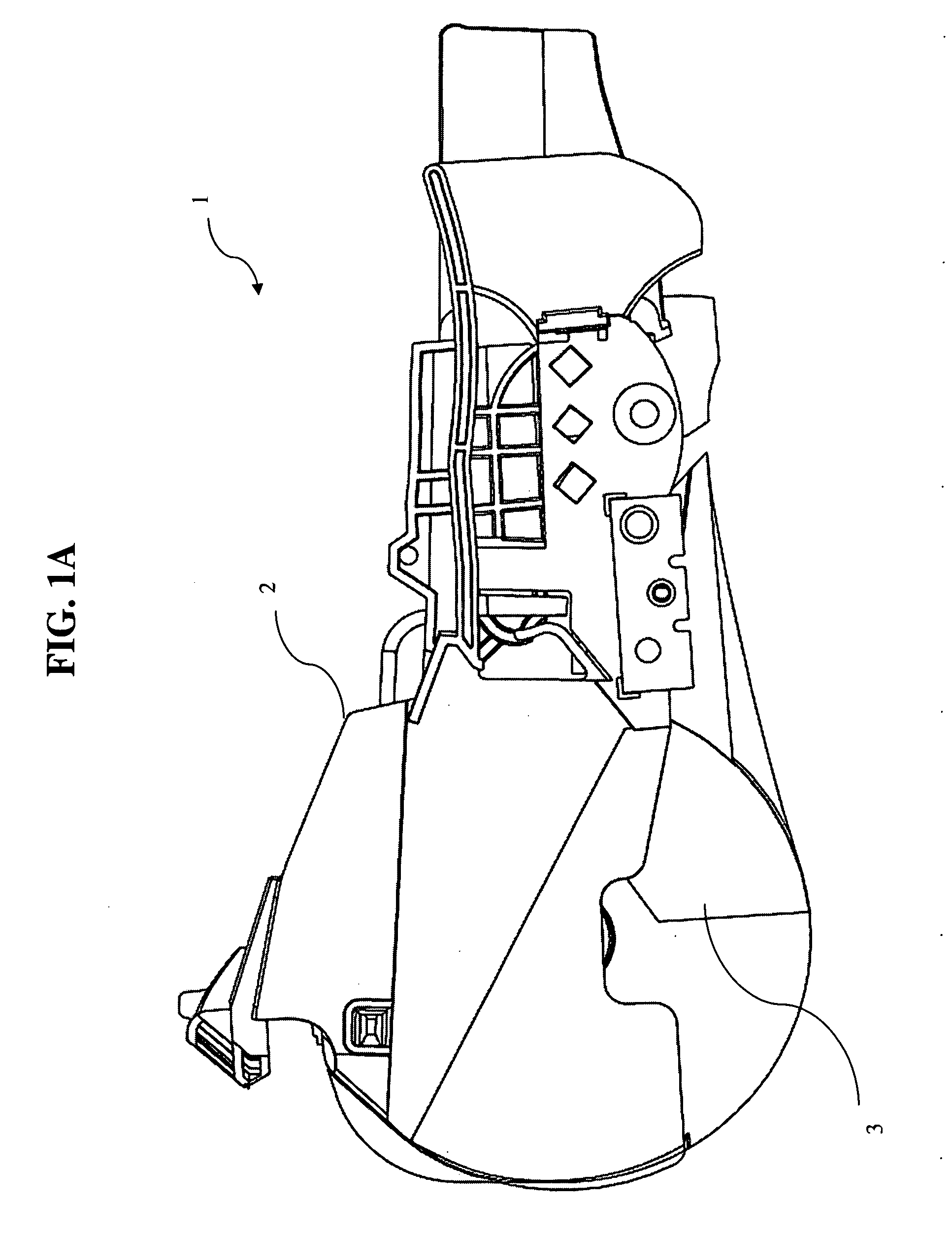
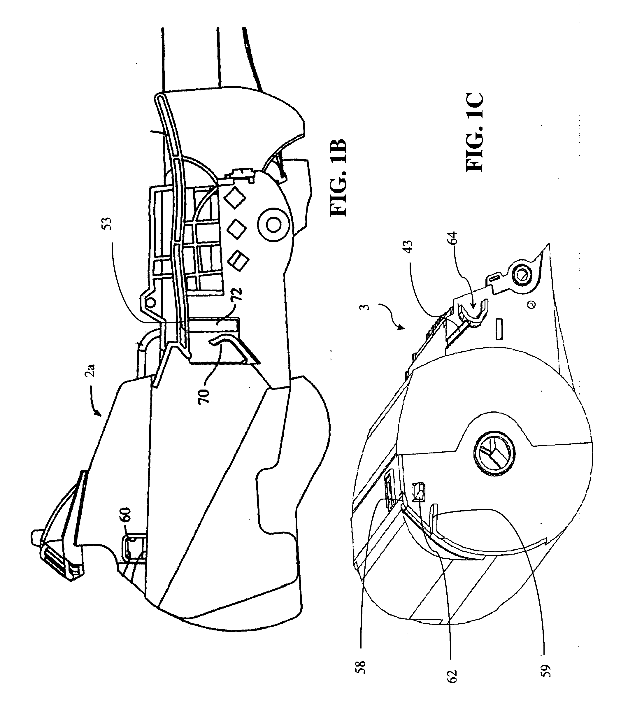
[0070]Hopper pin horizontal retainer 70 and hopper pin vertical lock 72 are formed integrally with waste bin 2 and cooperate with one another to engage hopper pin 64FIG. 3 as best understood in connection with FIGS. 1B and 1C.

[0071]When hopper pin 64 is engaged in horizontal retainer 70 and hopper pin vertical lock 72, its captured position dictates the elevation of the rear of planar wing 53 as depicted in FIG. 1B. Horizontal retainer 70 exerts an upward force on curved surface 64a of hopper pin 64, causing upper locating surface 64b to make snug contact at a point on the bottom side of level planar wing 53 (FIG. 4A). Such snug contact ensures proper alignment and orientation of cartridge components when the cartridge is installed into and removed from the printer. The leveling of the planar wing provides ...

second embodiment

[0087]A second embodiment, shown in FIGS. 10A through 10C, contact spring 121b accepts step-down 123a on adder roller shaft 123. In this manner, good conductivity is made between contact spring 121b and adder roller shaft 123. Contact spring 121b then bridges the gap between side wall 3b of hopper 3 and contact plate 130 on outer side wall 2b of waste bin 2 (FIGS. 10B and 10C).

[0088]Contact spring 116b accepts step-down 118a on developer roller shaft 118. In this manner, good conductivity is made between contact spring 116b and developer roller shaft 118. Contact spring 116b then bridges the gap between side wall 3b of hopper 3 and contact plate 130 on outer side wall 2b of waste bin 2 (FIGS. 10B and 10C).

[0089]In all embodiments, illustrated in FIGS. 10B and 11B, contact blade 111 makes electrical contact with doctor bar 110 and is held in place by receiving slot 113 integral to hopper 3. Contact blade 111 is attached to connecting wire 111a that bridges the gap between side wall 3...

third embodiment

[0091]Turning now to FIGS. 11A through 11C, a third embodiment is shown wherein adder roller 120 has elongated shaft 121c that bridges the gap between side wall 3b of hopper 3 and contact plate 130 on outer side wall 2b of waste bin 2 by passing through hole 121d. Rounded tip 117a engages with conductive spring 119a, generally a folded conductive element but any conductive biasing means is contemplated. Folded spring 119a communicates with contact plate 130.

[0092]Developer roller 115 is adapted with elongated shaft 116c that bridges the gap between side wall 3b of hopper 3 and contact plate 130 on outer side wall 2b of waste bin 2 by passing through hole 118d. Rounded tip 117 engages with conductive spring 119, generally a folded conductive element but any conductive biasing means is contemplated. Folded spring 119 communicates with contact plate 130.

[0093]As with the previous embodiments, illustrated in FIGS. 10B and 11B, contact blade 111 makes electrical contact with doctor bar 1...


PUM


Abstract

Provided is an improved drive mechanism for an imaging machine. A tapered surface is disposed outboard of the drive dog seat whereby a tooth of the imaging machine drive mechanism is centered and directed into the drive dog seat. The leading edge of the drive dog seat contacts the base of the imaging machine drive mechanism thus making full contact between the drive dog seat and the imaging machine drive mechanism tooth.

Description

CROSS REFERENCE TO RELATED APPLICATIONS[0001]This application is a divisional of co-pending U.S. patent application Ser. No. 11 / 120,685 entitled: “Toner Hopper Interconnection,” filed May 3, 2005 which is a continuation-in-part to U.S. patent application Ser. No. 10 / 907,470 entitled: “Integrated Toner Cartridge with Toner Agitator and Sensing Device,” filed Apr. 1, 2005, now U.S. Pat. No. 7,177,567, which is a continuation of U.S. patent application Ser. No. 10 / 742,323 entitled: “Removable Toner Cartridge Universal Adapter,” filed Dec. 19, 2003, now U.S. Pat. No. 7,136,608.BACKGROUND OF THE INVENTION[0002]Laser printers use a coherent beam of light, hence the term “laser printer,” to expose discrete portions of an image transfer drum thus attracting the printing toner. Toner is a mixture of pigment (most commonly black) and plastic particles. The toner becomes electro-statically attracted to exposed portions of the image transfer drum. The toner is transferred to paper, or other med...

Claims


Application Information

Patent Timeline
Patent Type & Authority Applications(United States)
IPC IPC(8): G03G15/00G03G15/08
CPCG03G15/0894G03G15/0896G03G21/12G03G21/1821G03G21/1867G03G21/1878G03G15/0855G03G2215/0697G03G2221/166G03G2221/1823G03G15/0868G03G15/0865G03G21/1896
Inventor MILLER, STEVEN
Owner MILLER STEVEN
Why Eureka
Try Eureka