Humidifier for fuel cell and process for warming the same

a fuel cell and heater technology, applied in the direction of cell components, lighting and heating apparatus, heating types, etc., can solve the problem that the gas supply cannot be supplied to the fc, and achieve the effect of enhancing the electrochemical reaction, and reducing the cost of gas consumption

Active Publication Date: 2008-06-26
HONDA MOTOR CO LTD
View PDF5 Cites 11 Cited by
  • Summary
  • Abstract
  • Description
  • Claims
  • Application Information

AI Technical Summary

Benefits of technology

[0022]According to the humidifier of the present invention, which comprises a pair of heads of which hold both ends of hollow fiber membrane modules comprising hollow fiber membranes, a connecting member which connects each of heads, and a device for warming the supply gas (hereinafter referred to as “a hot water riser”), can enhance a humidification efficiency due to heat exchange with a high efficiency and can humidify the supply gas in an appropriate manner.
[0027]According to the process for warming a humidifier of the present invention, in the process for warming a humidifier having a hot water riser, the outlet side of the supply gas of the cathode side humidifier can be warmed first by a cooling medium, which just exits from the fuel cell and which is warmed. Consequently, the temperature of the supply gas immediately before being supplied to the fuel cell may be substantially the same temperature as that of the fuel cell itself, and then the supply gas having such a temperature can be supplied to the fuel cell. This makes it possible to enhance an electrochemical reaction in which oxygen and hydrogen are reacted to take an electric energy.
[0028]Also, since the outlet side of the supply gas of the cathode side humidifier can be warmed first by a cooling medium, which just exits from the fuel cell and which is warmed, the heat is difficult to be radiated. In addition, by warming the inlet side of the supply gas, the heat can be much more effectively utilized. For this reason, the enhancement of heat efficiency leads to enhancement of heat exchange. This can provide a fuel cell having enhanced heat exchange performance.

Problems solved by technology

However, in the conventional fuel cell system, there is a temperature difference between the temperature of the fuel cell (FC) itself and the temperature of the supply gas, which poses a problem that the supply gas cannot supply to FC at a temperature similar to the temperature of FC.

Method used


Image

  • Humidifier for fuel cell and process for warming the same
  • Humidifier for fuel cell and process for warming the same
  • Humidifier for fuel cell and process for warming the same

Examples


Embodiment Construction

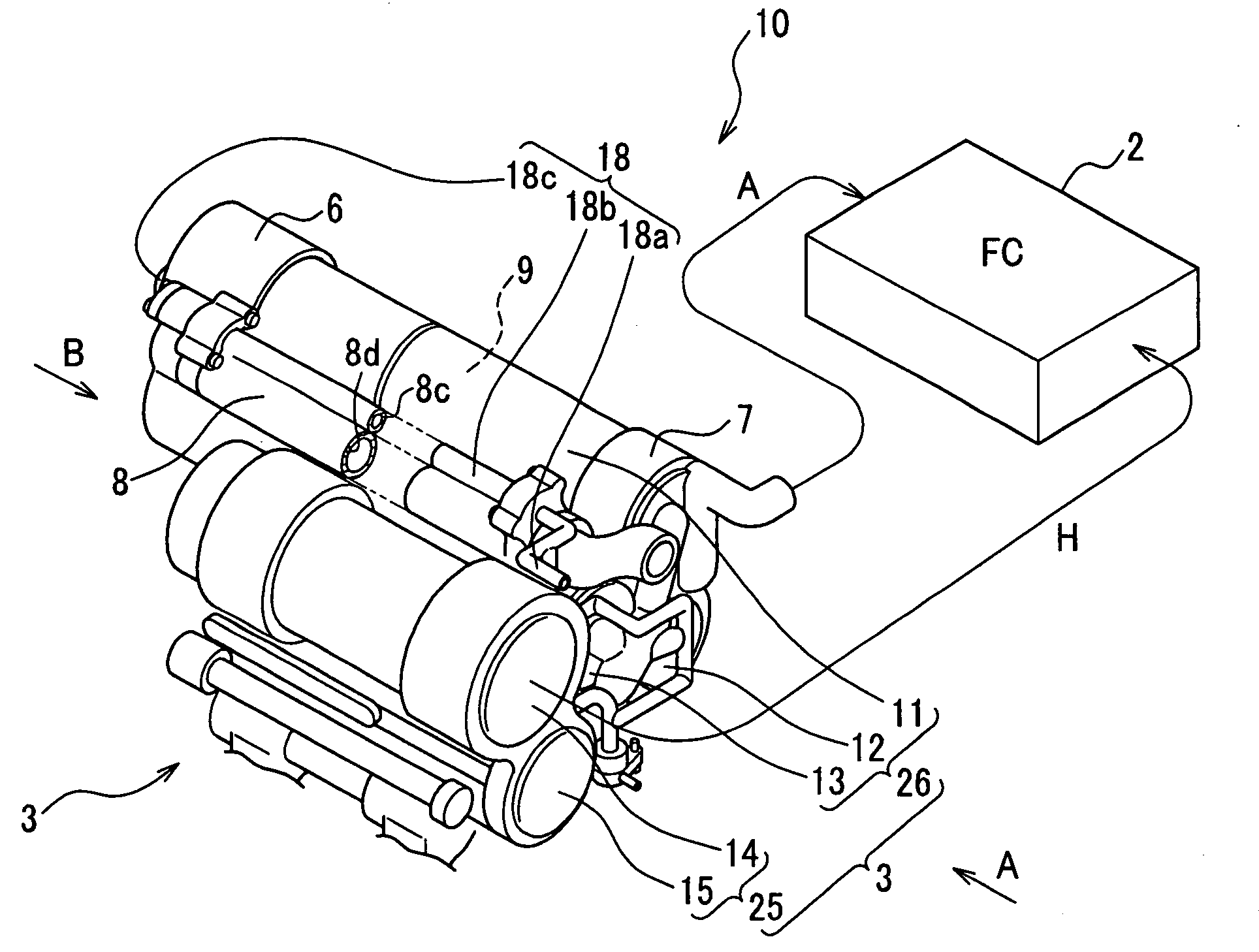
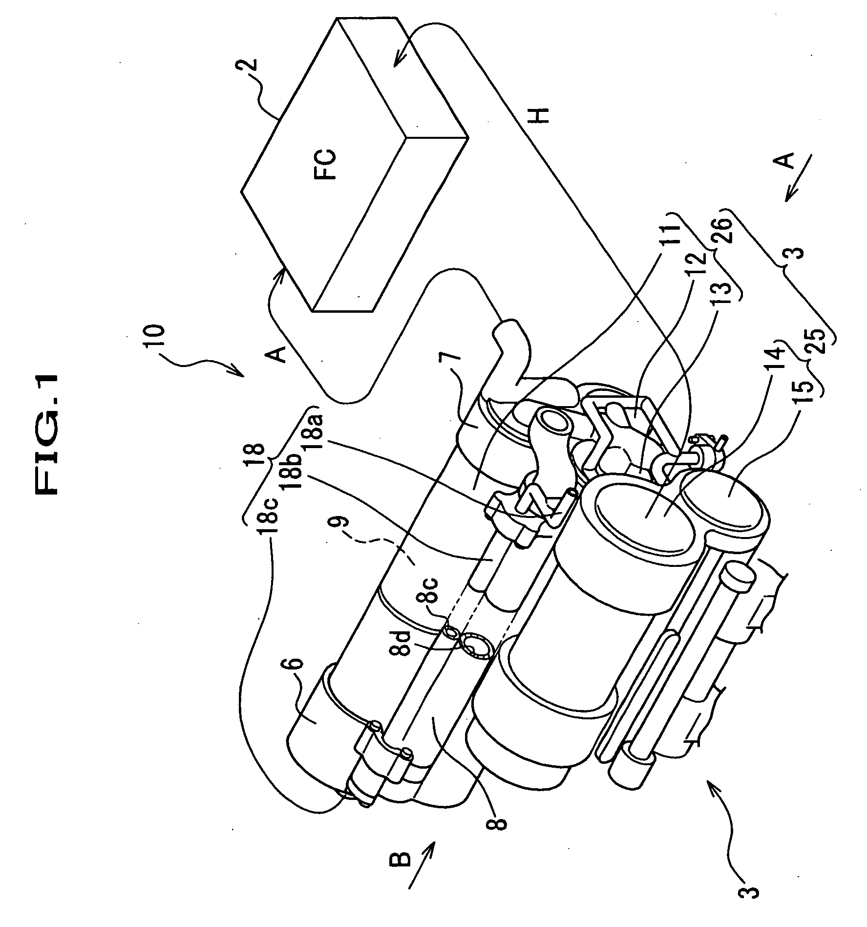
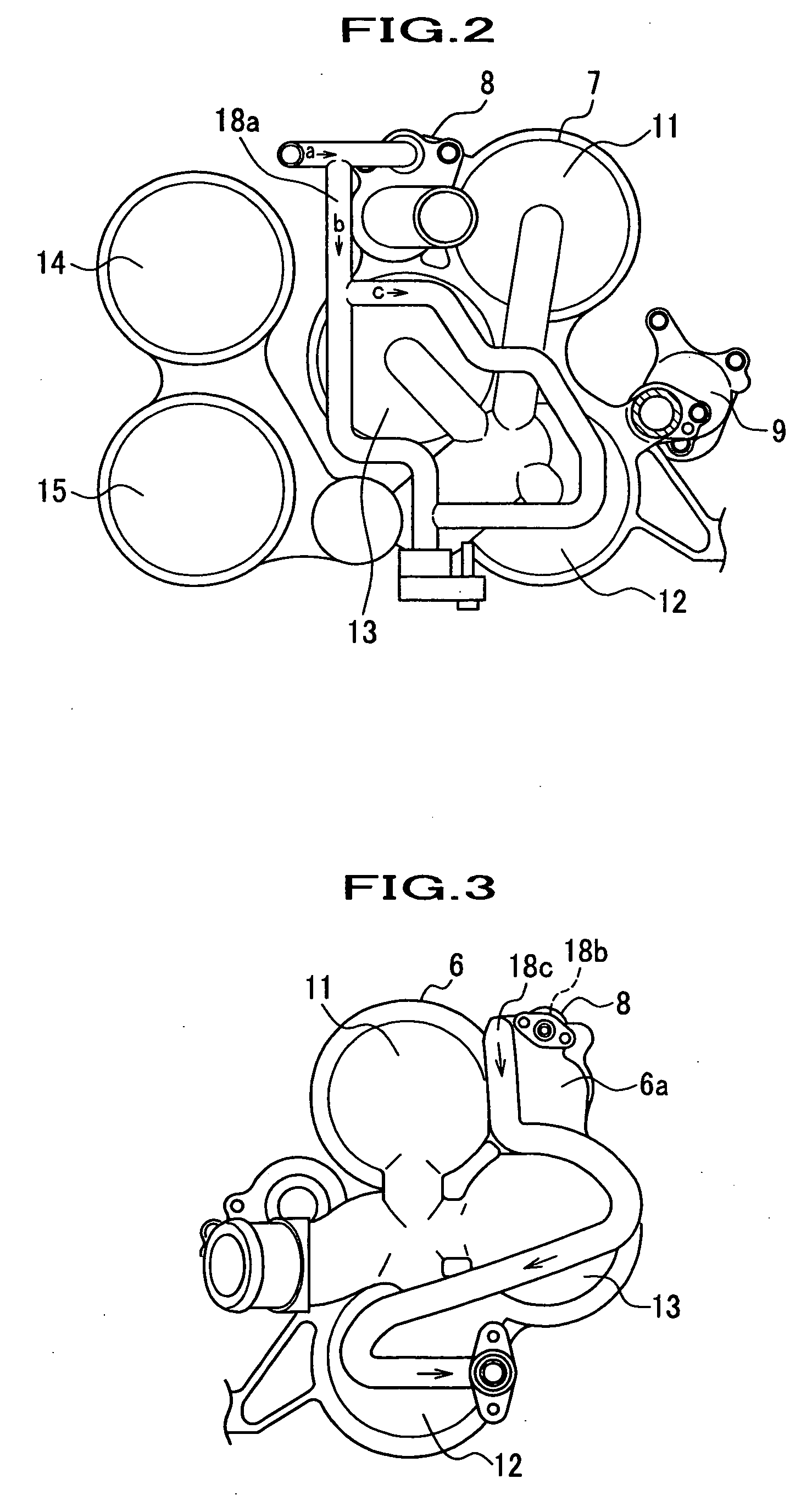
[0034]Referring to FIG. 1 to FIG. 3, one embodiment of the humidifier according to the present invention will now be described. This embodiment is an embodiment that the humidifier of the present invention is applied to a humidifier for a fuel cell which is provided on a fuel cell electric vehicle. FIG. 1 is a perspective view showing a fuel cell system composed of a fuel cell and a humidifier having a hot water riser. As shown in FIG. 1, the fuel cell system 1 is mainly composed of FC (fuel cell) 2, a humidifier 3, to humidify air and hydrogen, which are supply gases, and a capacitor (not shown) to storage electricity.

[0035]The term “hot water riser” used herein means a device for warming a supply gas to be supplied to the fuel cell by passing a hot water there-through. Specifically, the hot water riser means a device composed of conduits for transmitting a heat of the cooling medium (cooling water) to the humidifier, preferably as a counter flow against the supply gas to warm the ...


PUM

PropertyMeasurementUnit
temperatureaaaaaaaaaa
circumferenceaaaaaaaaaa
permeableaaaaaaaaaa

Abstract

A humidifier for humidifying a fuel cell composed of an anode side humidifier and a cathode side humidifier each possessing a plurality of hollow fiber membrane modules for migrating moisture between a supply gas, which is supplied to a fuel cell, and an exhaust gas, which is exhausted from the fuel cell to thereby humidify the supply gas, the humidifier comprising: a pair of heads which hold both ends of the hollow fiber membrane modules, a connecting member which connects each of heads, and a device for warming the supply gas composed of conduits through which a cooling medium exhausted from the fuel cell is passed. The device for warming the supply gas is configured so that first warms a humidifier at an outlet side of the supply gas, and then warms a humidifier at an inlet side of the supply gas.

Description

RELATED APPLICATIONS[0001]The present application is a divisional of U.S. patent application Ser. No. 10 / 714,464 filed Nov. 14, 2003 (now allowed) which claims priority to Japanese Application No. JP 2002-331205 filed Nov. 13, 2002.BACKGROUND OF THE INVENTION[0002]1. Field of the Invention[0003]The present invention relates to a humidifier for fuel cell utilizing water-permeable type hollow membranes and a process for warming the same.[0004]2. Description of the Related Arts[0005]A fuel cell which is carried on an automobile or such is composed of a lamination of a polymer membrane electrolyte assembly (hereinafter sometimes referred to as “MEA”) having an anode and a cathode provided on both surfaces thereof; gas passages each for supplying a reactant gas formed on both surfaces of the MEA; and separators which support MEA from both sides. In order to allow hydrogen ions for easily flowing within MEA, a humidifier is placed, which humidifies hydrogen and oxygen for being supplied w...

Claims


Application Information

Patent Timeline
Patent Type & Authority Applications(United States)
IPC IPC(8): H01M8/02H01M8/10F24F3/14H01M8/00H01M8/04
CPCH01M8/04029Y02E60/50H01M8/04126
Inventor KUSANO, YOSHIOKATAGIRI, TOSHIKATSUSUZUKI, MOTOHIRONAGUMO, KENJI
Owner HONDA MOTOR CO LTD
Why Eureka
Try Eureka