
Means and Device for Compensating a Local Deformation of the Cornea of an Eye

Inactive Publication Date: 2008-06-26
TOMALLA KARIN +1
View PDF2 Cites 0 Cited by
  • Summary
  • Abstract
  • Description
  • Claims
  • Application Information

AI Technical Summary

Benefits of technology

[0011]The invention features, in one embodiment, a means of the type mentioned at the outset allowing improved compensation, compared to the prior art, for local deformation of the cornea of an eye. Also to be specified is a device of the type mentioned at the outset which minimises, with improved compensation for a local deformation of the cornea, undesirable side effects and / or repercussions for the patient.

Problems solved by technology

This leads to a change in refraction with in some cases substantial distortions of the cornea (astigmatisms) for which neither glasses nor contact lenses are able to compensate satisfactorily.
Severely restricted sight is the result.
Operating methods of this type have the drawback, in particular, of requiring patient convalescence and aftercare lasting several months.
Further drawbacks include the scarring effects resulting from lacerations and the resultant astigmatism.
There are also often introduced into the respective receptacle, during preparation, epithelial cells which can produce undesirable deposits on the INTACS.
The endothelial cells extending on the inside of the cornea are also inevitably damaged during carrying-out of the known operating method owing to the tensile and compressive loads.
A further drawback of this operating method is that, owing to the fixed incision width, there is no variability on introduction of the channels for the implants, and this can cause more or less pronounced stress in the treated cornea.
The known method therefore often does not provide sufficiently precise compensation for the local deformation of the cornea and, in particular, the complex stress conditions occurring in the region of the deformation, so the deformation also cannot be optimally eliminated.

Method used


Image

  • Means and Device for Compensating a Local Deformation of the Cornea of an Eye
  • Means and Device for Compensating a Local Deformation of the Cornea of an Eye
  • Means and Device for Compensating a Local Deformation of the Cornea of an Eye

Examples


Embodiment Construction

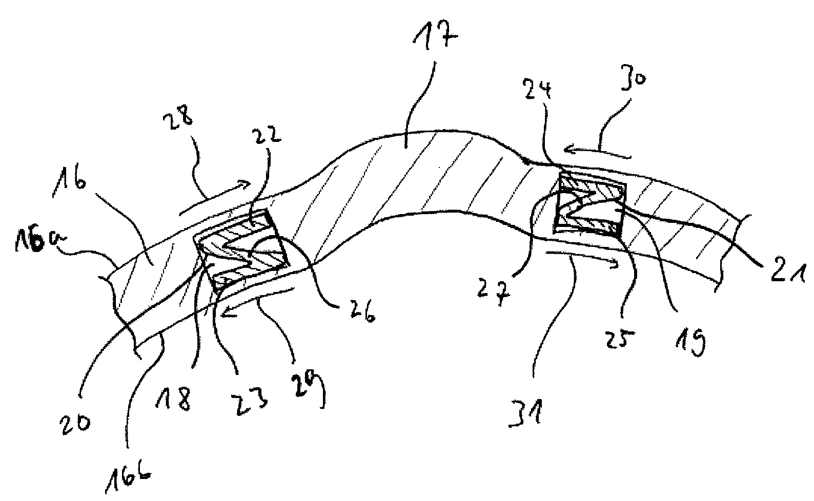
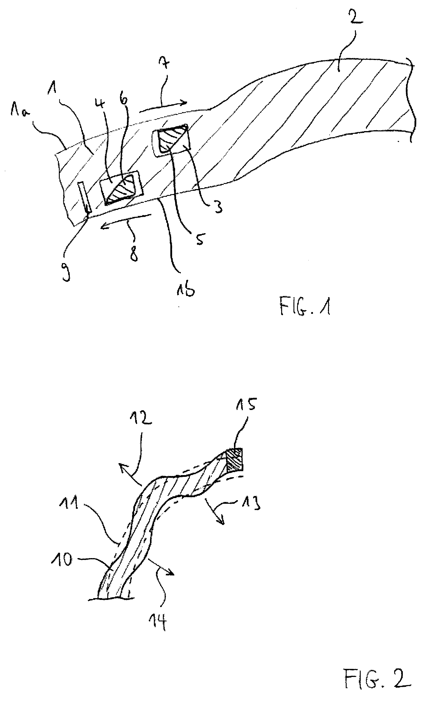
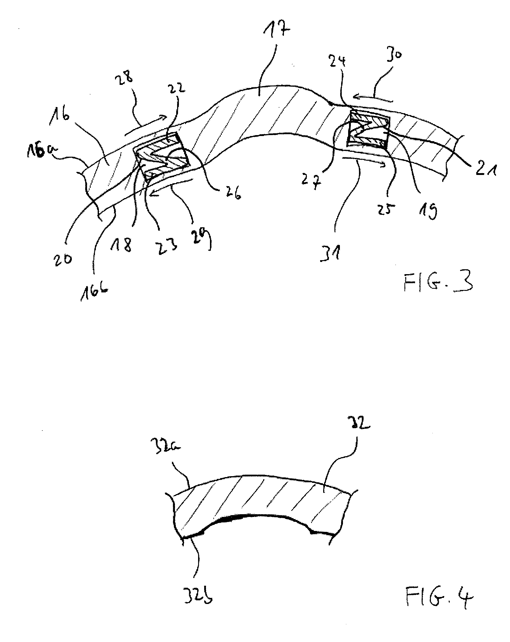
[0063]FIG. 1 is a cross section of a detail of the cornea 1 of a human eye. The cornea has a distal surface 1a and a proximal surface 1b facing the retina of the eye. In the cornea 1, a local deformation 2 is formed in the form of a circularly delimited arching. In the non-deformed, healthy region of the cornea 1, two channel-like receptacles 3, 4 have been formed using a femtosecond laser.

[0064]The receptacles 3, 4 have a rectangular cross section and are of circle-arcuate shape in their longitudinal extension. They each encompass an angular range of less than 180°. The centre of curvature of the receptacles 3, 4 is located in this case approximately on an axis (not shown) running through the centre of the deformation 2. The receptacle 3 is inserted in a distal plane of the cornea 1 and the receptacle 4 is inserted in a proximal plane of the cornea 1.

[0065]For compensating for the deformation 2 of the cornea 1, implant members 5, 6, each made of PMMA, are inserted into the receptac...


PUM


Abstract

A local deformation of the cornea of an eye can be compensated by a set comprising at least two implant members for insertion into at least one receptacle inserted into the cornea, wherein at least two implant members are arranged in differing planes located one above the other. Undesirable repercussions and side effects of the intervention in the eye can be detected as early as the simulation takes place and suitable receptacles and the like can be accordingly selected in order to minimise such repercussions and side effects and, at the same time, to provide optimum compensation for the deformation of the cornea in order to compensate for the deformation.

Description

CROSS-REFERENCE TO RELATED APPLICATIONS[0001]This application is a National Phase Application of International Application No. PCT / EP2006 / 060199, filed Feb. 23, 2006, which claims the benefit of and priority to German Application No. 10 2005 009 259.4, filed Feb. 25, 2005, which is owned by the assignee of the instant application. The disclosure of each of the above applications is incorporated herein by reference in its entirety.FIELD OF THE INVENTION[0002]The present invention relates to a means and a device for compensating for a local deformation of the cornea of an eye. A means of this type and a device of this type are used for compensating for a local deformation of the cornea of the eye, especially of the human eye. However, they can also be used for treating the eye of a different creature.BACKGROUND OF THE INVENTION[0003]Owing to diseases and / or injuries, the cornea of a human eye can experience reductions in thickness causing, under the influence of the aqueous humour pre...

Claims


Application Information

Patent Timeline
IPC IPC(8): A61F2/14
CPCA61F2/147A61F2/14
Inventor TOMALLA, MARKTOMALLA, GEBHARD
Owner TOMALLA KARIN
Learn More