Razors

Inactive Publication Date: 2008-07-03
THE GILLETTE CO
View PDF43 Cites 67 Cited by
  • Summary
  • Abstract
  • Description
  • Claims
  • Application Information

AI Technical Summary

Benefits of technology

[0009]By accommodating the motor within the pivotal head structure the transmission between the motor and a mo

Problems solved by technology

When the motor driven device is located at a head of the razor and remote from the handle, the transmission can be complicated, especially if a component of blade unit is to be reciprocally driven.
To transmit motion from a motor housed in the razor handle to a component of a

Method used


Image

  • Razors
  • Razors
  • Razors

Examples


third embodiment

[0045]a safety razor illustrated in FIGS. 14-17 is fundamentally the same as the previous two embodiments inasmuch that it has a head structure 5 pivotally mounted to a pair of yoke arms 2 extending from the upper end of the razor handle 1. In this embodiment a separate connection tube between the handle and the head structure for leading electric cable conductors from the handle to the head structure could be included but is not shown and in this embodiment the electrical conductors for delivering electric current from the battery accommodated in the handle to the motor 18 within the head structure are taken through at least one of the pivoted connections between the head structure 5 and the yoke arms 2. The head structure 5 includes a hollow body 6 defining a chamber that is closed by a top cover 15 to form a sealed motor housing 9. The electric motor 18 is fixedly mounted within the sealed chamber of the motor housing 9 and its rotary output shaft 19 carries an eccentric cam elem...

fourth embodiment

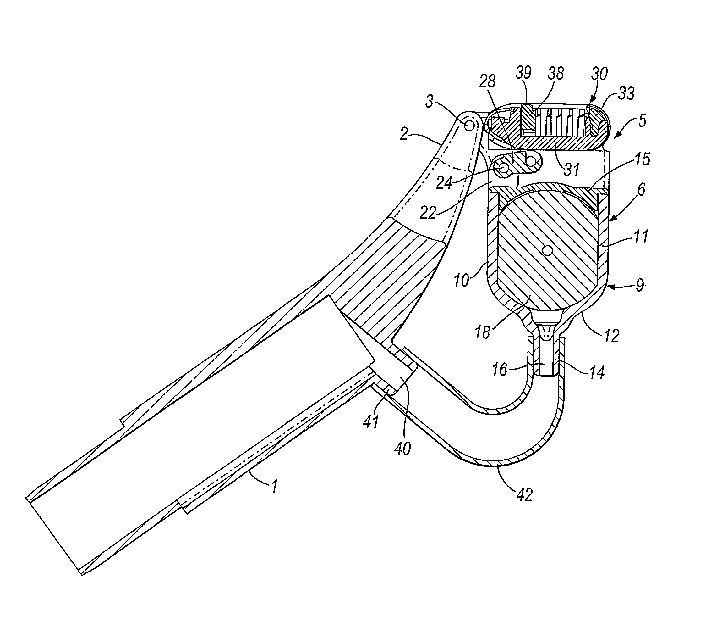
[0047]a safety razor illustrated in FIGS. 18-22, like the previous embodiments, has a head structure 5 pivotally mounted to the upper end of a handle 1 by a pair of yoke arms 2 for pivoted movement about an axis A with respect to the handle. The head structure 6 includes a motor housing 9 sealed closed at the top by a cover 15. The motor 18 is firmly positioned within the chamber enclosed by the motor housing and a frame 80 carrying a pair of aligned pins 81 is fitted around the motor 18. A drive member 82 is journalled on the pins 81 and is coupled to the output drive shaft 19 of the motor 18 to be oscillated about the axis of the pins 81 when the motor is energised. The motor drive shaft 19 carries an eccentric cam element that is engaged in a hole in a pin 83. The drive member 82 includes a driving pin 85 that projects through an arcuate slot 84 in the cover 15 and is sealed to the cover by a flexible seal not shown, the pin 85 being reciprocated along an arcuate path when the mo...


PUM


Abstract

A safety razor has a handle (1) and a head structure (5) mounted for pivotable movement relative to the handle during shaving. The head structure (5) includes a motor (18) housed in a sealed chamber (9) for driving a device in use of the razor, such as to reciprocate a guard component or a blade, to vibrate the head structure, to actuate a dispensing device for delivering a shaving enhancement fluid, or to oscillate a support platform (101) on which a blade unit (110) is mounted. The shaving cartridge can include a guard component (38) with projections (39) which are moved towards and away from the skin being shaved when the guard component is reciprocated by the motor (18).

Description

FIELD OF THE INVENTION[0001]This invention is concerned with razors and in particular relates to safety razors including electric motors.BACKGROUND OF THE INVENTION[0002]Safety razors generally comprise a handle by means of which one or more blades with sharp cutting edges are moved across the surface of the skin in performing a shaving stroke with the razor. There have been many proposals to include an electric motor in a safety razor, for example, for driving a vibration mechanism, e.g. an eccentric weight, for vibrating the razor when it is in use, as described for example in U.S. Pat. No. 5,299,354 (Metcalf), or for moving a component of a blade unit mounted on the razor handle as described in EP-A-0906814 (Orloff), WO-A-96 / 25276 (Avidor) (FIGS. 12-15) and WO-A-2004 / 018165 (Zuidervaart). In the prior art constructions the electric motor is housed within the razor handle and a transmission arrangement is generally needed to couple the output shaft of the motor to the device being...

Claims


Application Information

Patent Timeline
IPC IPC(8): B26B19/00B26B19/42B26B19/44B26B19/14B26B19/28B26B21/52B26B21/22B26B21/40
CPCB26B21/222B26B21/38B26B21/405B26B21/4018B26B21/40
Inventor ROYLE, TERENCE GORDON
Owner THE GILLETTE CO
Why Eureka
Try Eureka