Eureka AIR delivers breakthrough ideas for toughest innovation challenges, trusted by R&D personnel around the world.

Liquid separation membrane installation body

Active Publication Date: 2008-07-03
NGK INSULATORS LTD
View PDF6 Cites 6 Cited by
  • Summary
  • Abstract
  • Description
  • Claims
  • Application Information

AI Technical Summary

Benefits of technology

[0010]The present invention has been developed in view of the above-mentioned problem, and is characterized by providing a liquid separation membrane installation body capable of increasing a permeation flow rate of a liquid.
[0020]According to the liquid separation membrane installation body of the present invention, the permeation flow rate at a time when the liquid is separated can be increased. In particular, the present invention can suitably be used as a separation membrane which separates water or the like from a mixed liquid such as salt water, a water-alcohol mixed liquid, a water-acid mixed liquid or a water-alkali mixed liquid.

Problems solved by technology

A clay membrane disclosed in Patent Document 1 described above is a self-standing membrane, and therefore has a large membrane thickness, and thus it cannot be said that, for example, permeability of a liquid is satisfactory.
A clay membrane disclosed in Patent Document 2 described above is formed for separation of a gas, and is supposed to have a problem that a clay is dispersed again in the liquid and cannot be used for separation of a liquid.
A clay membrane disclosed in Non-Patent Document 1 described above has a large membrane thickness, and therefore has a problem that a permeation flow rate of the liquid cannot sufficiently be increased and a problem that a separation performance is difficult to be improved.

Method used


Image

  • Liquid separation membrane installation body
  • Liquid separation membrane installation body
  • Liquid separation membrane installation body

Examples


example 1

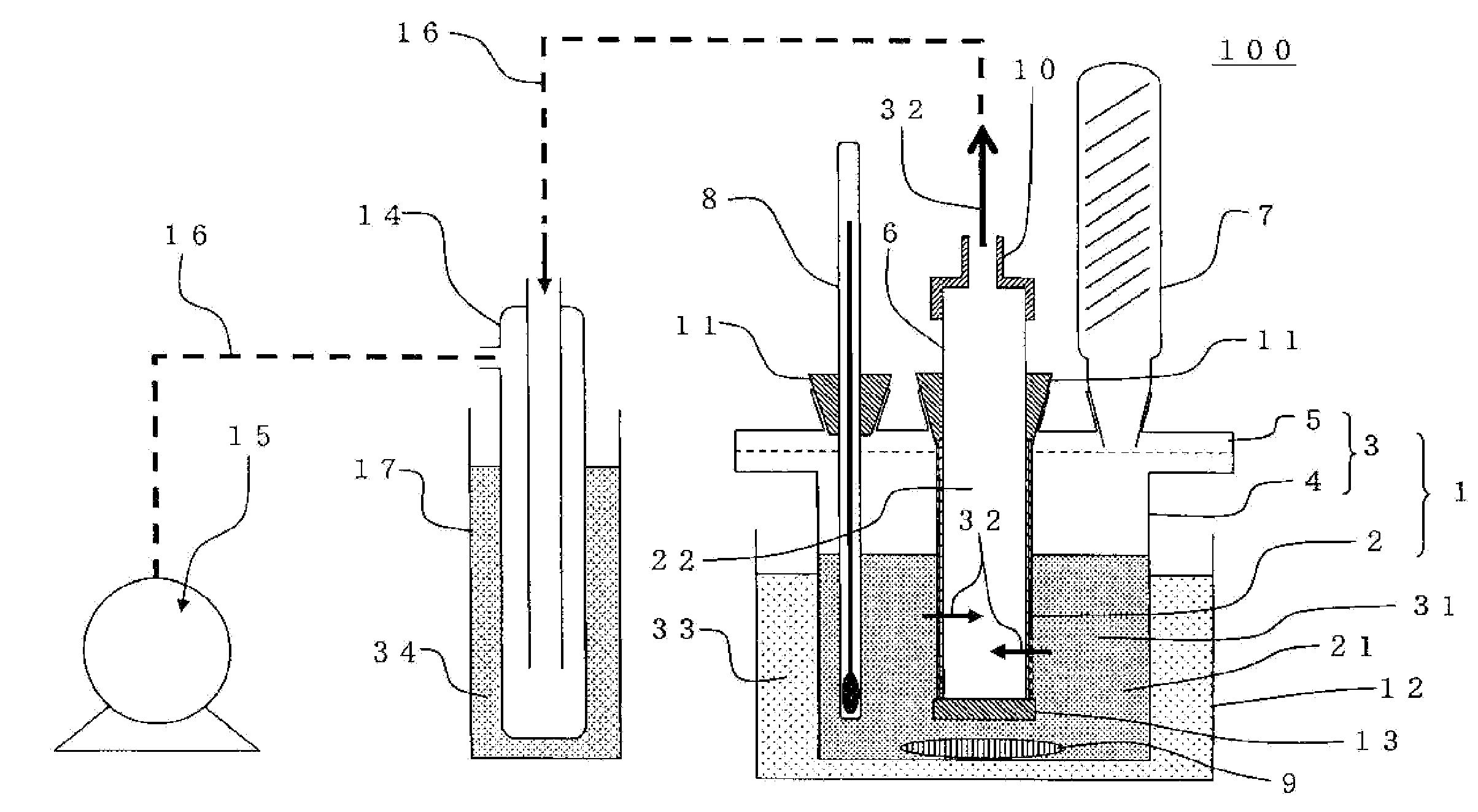
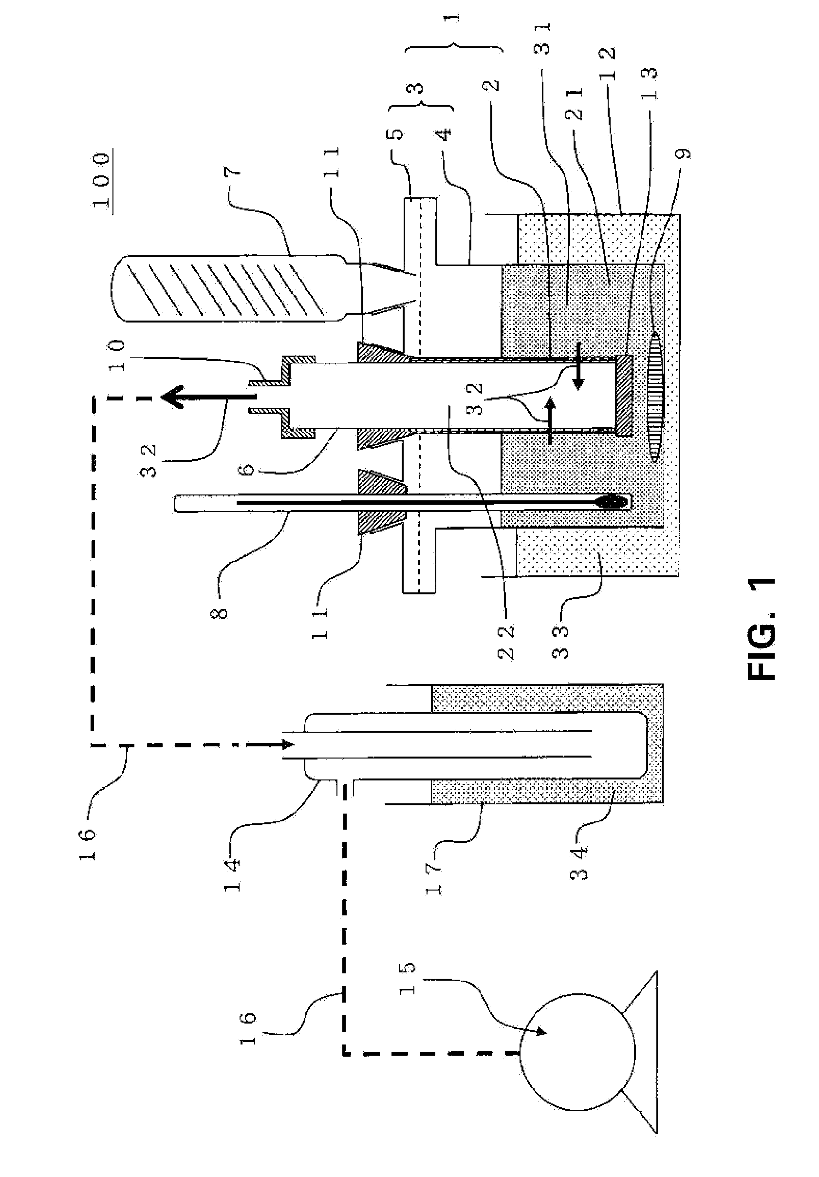
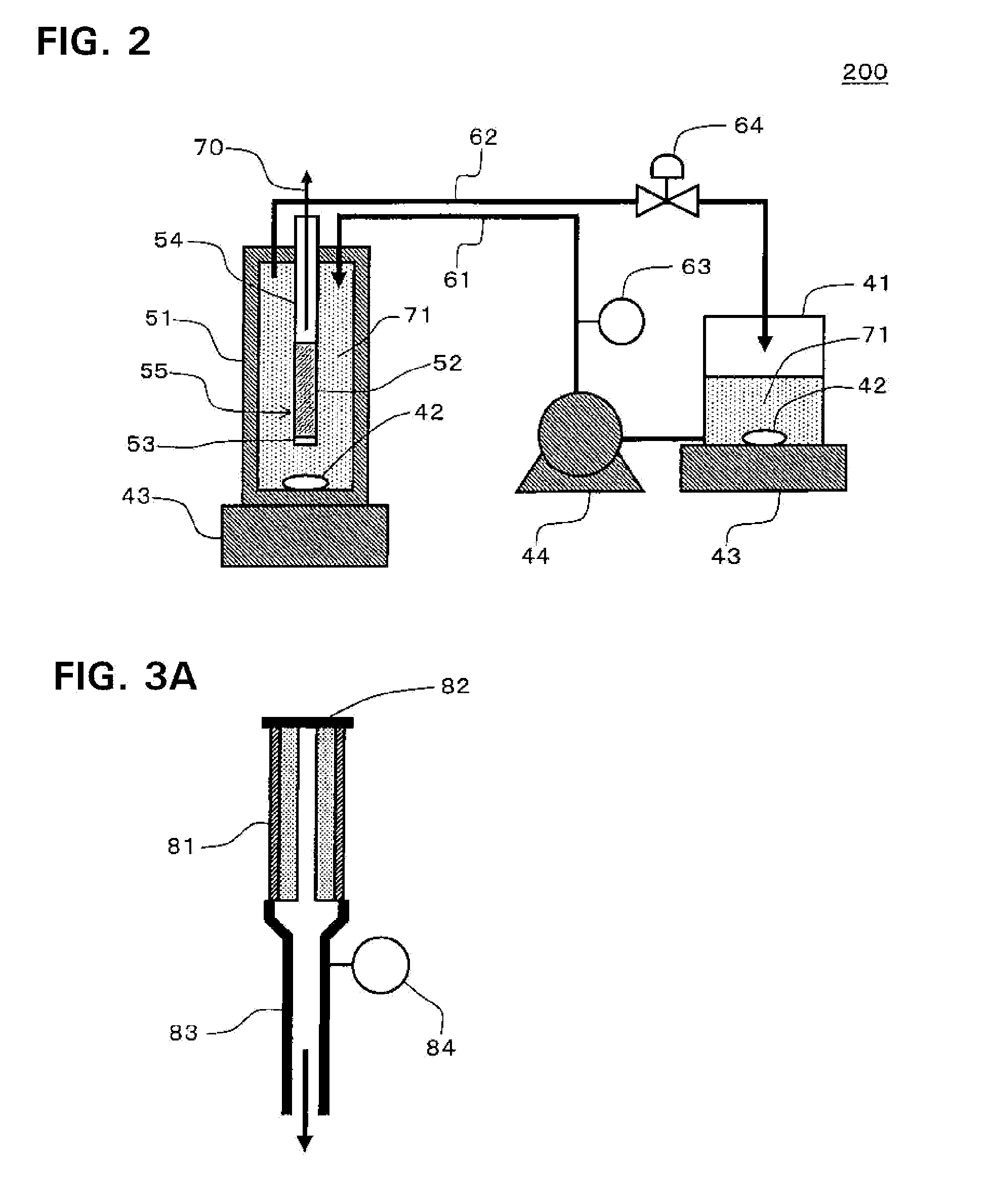
[0056]A liquid separation membrane installation body was prepared by the following method.

[0057](Porous Base Material)

[0058]A porous base material made of alumina and having a cylindrical tubular shape of a diameter of 10 mm×a length of 100 mm was used. The surface of the porous base material had pore diameters of 0.2 μm and a porosity of 30%.

[0059](Slurry Preparation)

[0060]As a dispersant layered inorganic compound, smectite powder was used. The smectite powder was added to pure water so as to obtain a concentration of 0.2%, and stirred using a stirrer for 24 hours to obtain a dispersion liquid. The smectite powder manufactured by Co-op Chemical Co., Ltd. and having a trade name: Lucentite was used.

[0061](Membrane Formation)

[0062]The dispersant layered inorganic compound (the smectite powder) was formed into a membrane on the surface of the porous base material by filtration membrane formation. A slurry in which the smectite powder was dispersed in water was allowed to flow into th...

example 2

[0065]A liquid separation membrane installation body (Example 2) was obtained in the same manner as in Example 1 except that a filtration time in a membrane formation step was set to 120 seconds. A membrane thickness was 1.0 μm.

example 3

[0066]A liquid separation membrane installation body (Example 3) was obtained in the same manner as in Example 1 except that a filtration time in a membrane formation step was set to 200 seconds. A membrane thickness was 1.4 μm.


PUM

PropertyMeasurementUnit
Pore sizeaaaaaaaaaa
Thicknessaaaaaaaaaa
Thicknessaaaaaaaaaa

Abstract

A liquid separation membrane installation body includes a porous base material, and a liquid separation membrane provided on the porous base material, the liquid separation membrane is a porous membrane formed of a dispersant layered inorganic compound, and a membrane thickness of the liquid separation membrane is 0.1 to 1.5 μm. The liquid separation membrane is preferably formed of a sheet-like dispersant layered inorganic compound which has a thickness of 0.1 to 100 nm, a major diameter of 0.01 to 5 μm and an aspect ratio (the major diameter / the thickness) of 3 or more and which is formed into the membrane on the porous base material. There is disclosed the liquid separation membrane installation body capable of increasing a permeation flow rate of a liquid.

Description

TECHNICAL FIELD[0001]The present invention relates to a liquid separation membrane installation body. More particularly, it relates to a liquid separation membrane installation body capable of increasing a permeation flow rate of a liquid.BACKGROUND ART[0002]Heretofore, a method for performing separation by use of a clay has been suggested. For example, it is disclosed that the clay is formed into a sheet-like self-standing membrane and can be used as a separation membrane (a clay membrane) (for example, see Patent Document 1). Moreover, a separation method, which uses a clay membrane formed on a base material but which has a purpose of separation of a gas, is disclosed (for example, see Patent Document 2). An example is disclosed in which a 2 μm clay membrane is formed on the base material to separate salt in salt water (for example, see Non-Patent Document 1).[0003]Furthermore, it is reported that the clay membrane is treated to synthesize a mesoporous material (for example, see P...

Claims


Application Information

Patent Timeline
IPC IPC(8): B01D29/00B01D39/00
CPCB01D61/02B01D61/362B01D67/0041B01D2325/04B01D69/04B01D69/14B01D71/028B01D67/0046B01D67/00411B01D71/0281
Inventor NODA, KENICHINIINO, MAKIKOYABUKI, MIYUKI
Owner NGK INSULATORS LTD
Why Eureka
Eureka Blog
Learn More