Resistance welding method and conductor unit

a resistance welding and conductor technology, applied in the field of resistance, can solve the problems of low mechanical strength of parts of objects, inconvenient connection of electric wires by using solder, and easy separation of welded parts of objects, so as to prevent deterioration

Active Publication Date: 2008-07-03
YAZAKI CORP
View PDF58 Cites 5 Cited by
  • Summary
  • Abstract
  • Description
  • Claims
  • Application Information

AI Technical Summary

Benefits of technology

[0019]Further, since no intermetallic compound is formed between the outer surface of the core member and the base member, therefore the mechanical strength of the welded part between the ou

Problems solved by technology

Since the intermetallic compound generally has low mechanical strength, therefore, when the objects to be welded together are connected by using the solder, a welded part of the objects has low mechanical strength, causing a problem that the welded part of the objects tends to easily separate.
This is a reason why such a method using solder is no

Method used


Image

  • Resistance welding method and conductor unit
  • Resistance welding method and conductor unit
  • Resistance welding method and conductor unit

Examples


Embodiment Construction

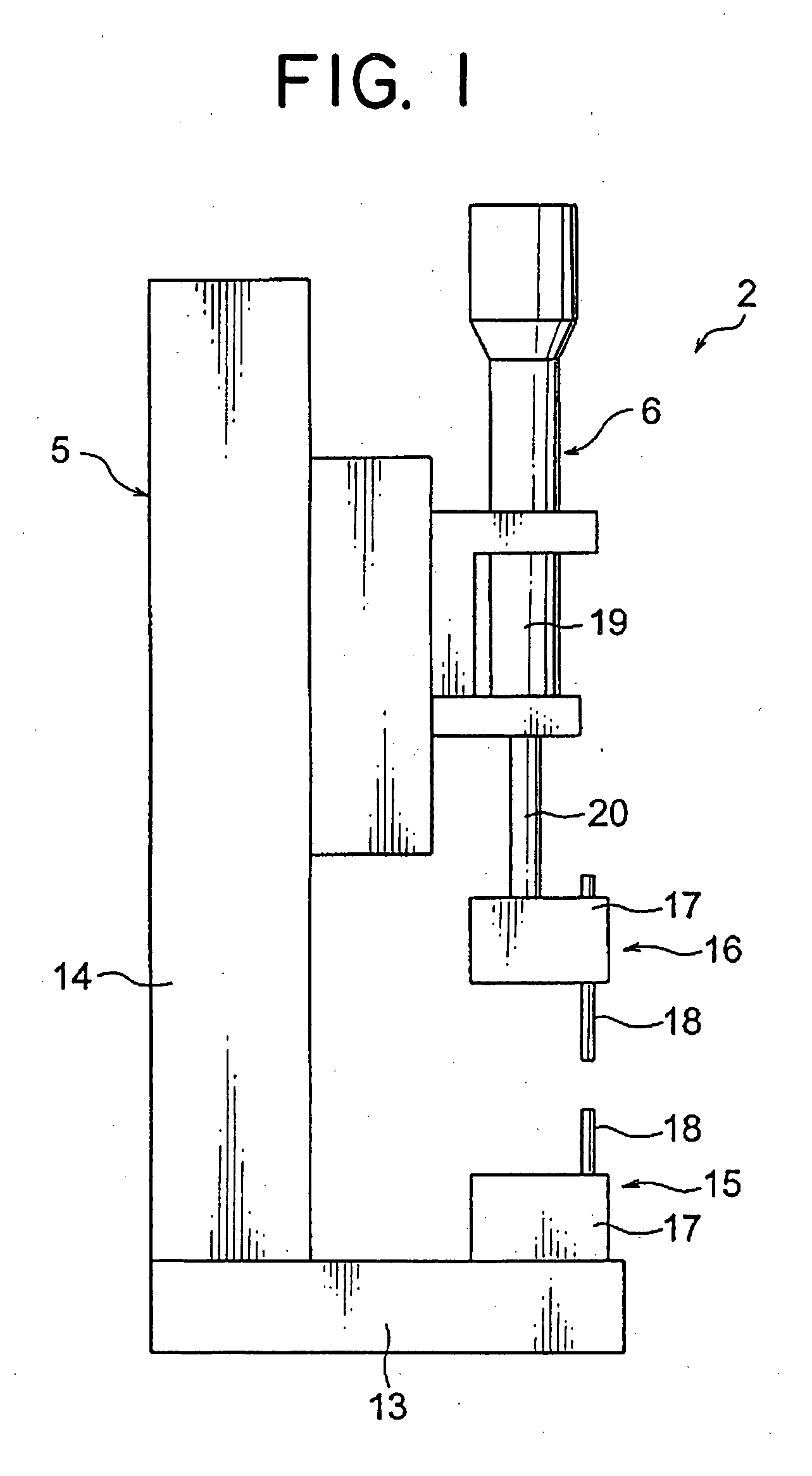
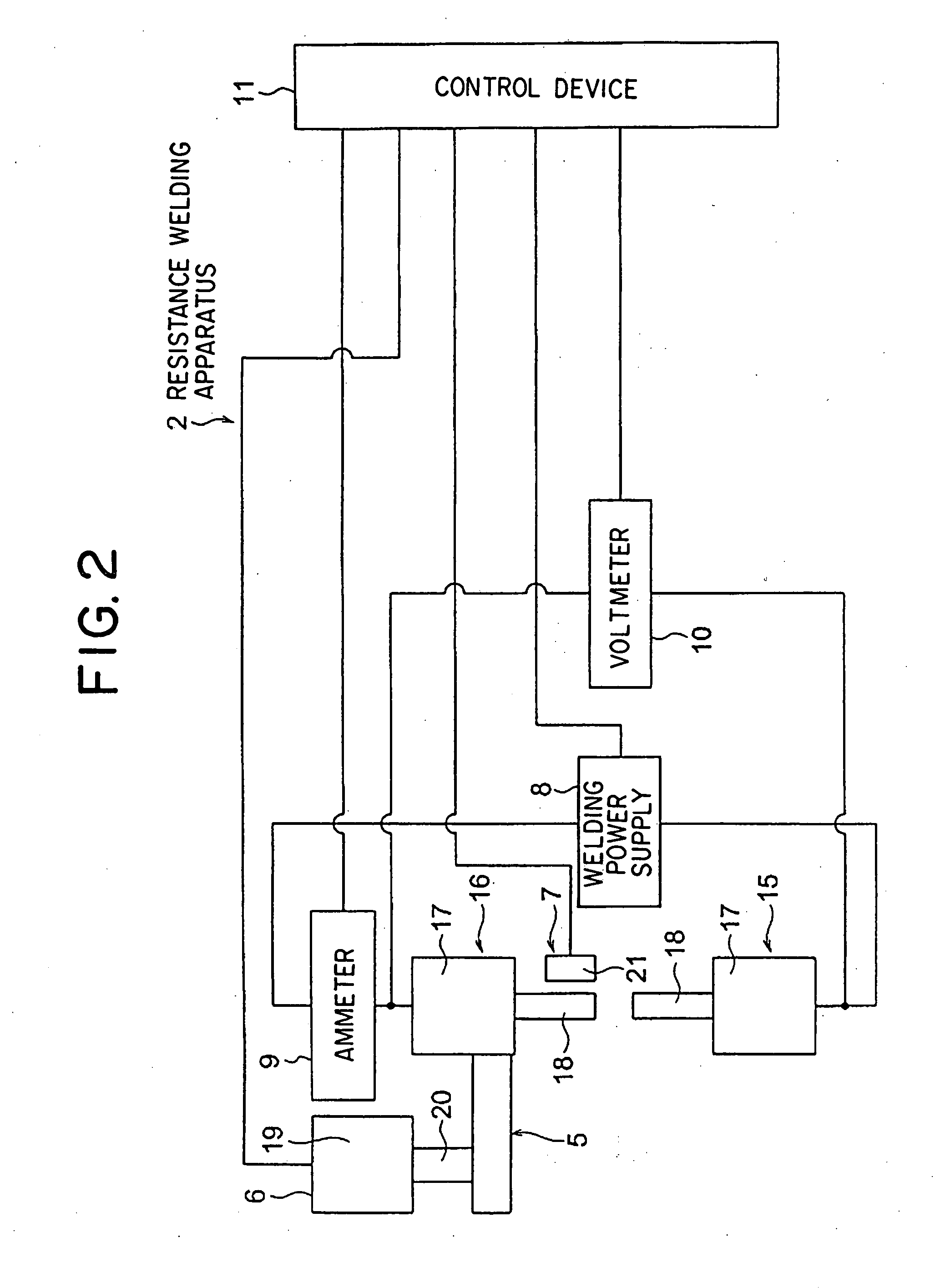
[0028]In the following, the preferred embodiments of the present invention will be explained with reference to FIGS. 1-8.

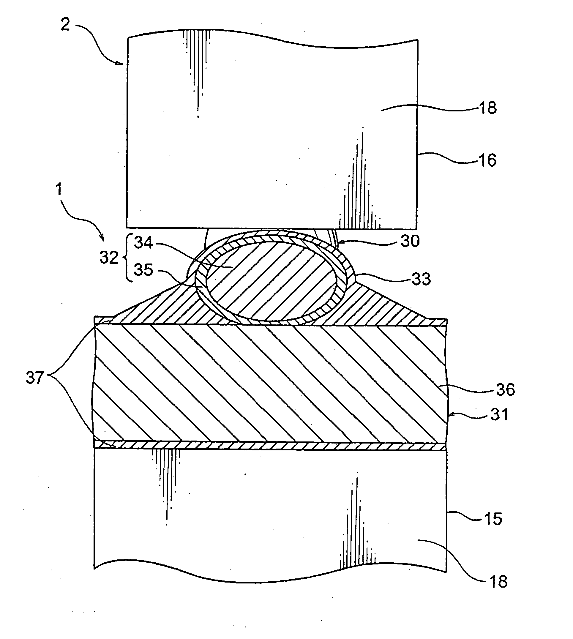
[0029]As shown in, FIG. 3, a conductor unit 1 includes an element wire 30 as one of the objects to be welded together and a metal plate 31 as another of the objects. As shown in FIG. 4, the element wire 30 includes a core member 32 and a plated layer 33 which coats the core member 32. The core member 32 is formed as a long wire having a round shape in section. As shown in FIG. 4, the core member 32 includes a core wire 34 and a coating layer 35 which coats the core wire 34.

[0030]The core wire 34 is made of metal or non-metal and formed as a long wire having a round shape in section. The core wire 34 is preferably made of a material having sufficient mechanical strength higher than that of the coating layer 35. The core wire 34 improves the mechanical strength of the core member 32. Of course, the core wire 34 may be made of a material having electrically conductiv...


PUM

PropertyMeasurementUnit
Currentaaaaaaaaaa
Melting pointaaaaaaaaaa

Abstract

The resistance welding method of welding two objects together includes the steps of: clamping the objects between a pair of electrodes; and applying a current between the electrodes while the objects are pressed to bring them close to each other to allow a contacting surface between them to generate heat. One object includes a core member and a plated layer coating the core member and having a melting point lower than that of a metal constituting an outer surface of the core member. The objects are clamped between the electrodes and the contacting surface are allowed to generate heat to melt the plated layer to weld the outer surface of the core member of the one object and a base member of another object together. At least the outer surface of the core member and the base member are made of respective metals, between which no intermetallic compound is formed.

Description

BACKGROUND OF THE INVENTION[0001](1) Field of the Invention[0002]The present invention relates to a resistance welding method for welding objects to be welded together such as an element wire having a plurality of coating layers and a metal piece and to a conductor unit, which is assembled by welding the objects together using the method.[0003](2) Description of the Related Art[0004]In order to electrically and mechanically connect (a) an element wire as an object to be welded which includes: a core material coated with an electrically conductive metal on an outer surface thereof; and a plated layer consisting of metal, such as tin, which coats the coated core material, to (b) a metal plate as another object to be welded which includes: a base material consisting of an electrically conductive metal; and a plated layer consisting of metal, such as tin, which is laminated on an outer surface of the base material, so far, for example, brazing using solder is applied or, alternatively, ...

Claims


Application Information

Patent Timeline
IPC IPC(8): B23K11/16
CPCB23K11/163B23K11/002
Inventor MURAKAMI, KAZUHIRO
Owner YAZAKI CORP
Why Eureka
Try Eureka