Multi-film compensated liquid crystal display with initial homogeneous alignment

a liquid crystal display and homogeneous alignment technology, applied in non-linear optics, instruments, optics, etc., can solve the problems of light leakage, the combination of c-film and a-film or single biaxial film does not achieve the desired symmetric viewing angle, and the cost of a-film is much higher than the cost of a-film

Inactive Publication Date: 2008-07-03
UNIV OF CENT FLORIDA RES FOUND INC +1
View PDF5 Cites 66 Cited by
  • Summary
  • Abstract
  • Description
  • Claims
  • Application Information

AI Technical Summary

Benefits of technology

[0011]A fourth objective of the present invention is to provide a compensation method to keep the normal view dark state of liquid crystal displays relatively unchanged.

Problems solved by technology

As a result, light leakage increases as the polar angle increases.
However, the cost associated with a C-film and a biaxial film is much higher than the cost of A-film.
Additionally, use of a combination of a C-film and an A-film or a single biaxial film does not achieve the desired symmetric viewing angle.

Method used


Image

  • Multi-film compensated liquid crystal display with initial homogeneous alignment
  • Multi-film compensated liquid crystal display with initial homogeneous alignment
  • Multi-film compensated liquid crystal display with initial homogeneous alignment

Examples


first embodiment

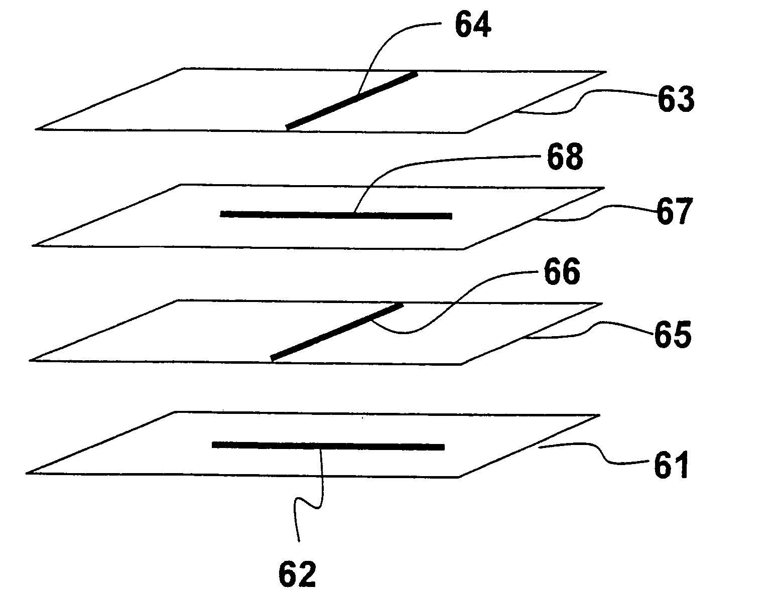
[0079]In a first embodiment, FIG. 10 illustrates the use of the multi-film compensation method and apparatus with an IPS-mode LCD, comprising a bottom polarizer 101 with a first absorption direction 102 and a top polarizer 109 with a second absorption direction 110 perpendicular to the first absorption direction 102 of the bottom polarizer 101, a homogeneously aligned liquid crystal (LC) layer 103 with its alignment direction parallel to the absorption direction 102 of the bottom polarizer 101, a positive A-film 105 with its optical axis 106 perpendicular to the absorption direction 102 of the bottom polarizer 101, a negative A-film 107 with its optical axis 108 perpendicular to the absorption direction 110 of the top polarizer 109.

[0080]The LC layer 103 is substantially homogeneously aligned at off-state when no voltage is applied to the LC layer 103 and forms a twist profile when driven by the lateral electric field generated from the comb-shaped electrodes. While FIG. 10 illustra...

second embodiment

[0084]In a second embodiment, the position of the positive A-film 105 and the negative A-film 107 are exchanged as illustrated in the schematic structure of FIG. 13. Table 3 lists the optimized film parameters for the positive A-film 105 and the negative A-film 107 used in the structure of FIG. 13.

TABLE 3RetardationFilm ThicknessFilm Birefringenceof filmFilm Type(μm)Δn = ne − nodΔn (nm)Positive A-film56.50.001584.8Negative A-film61.5−0.0015−92.3

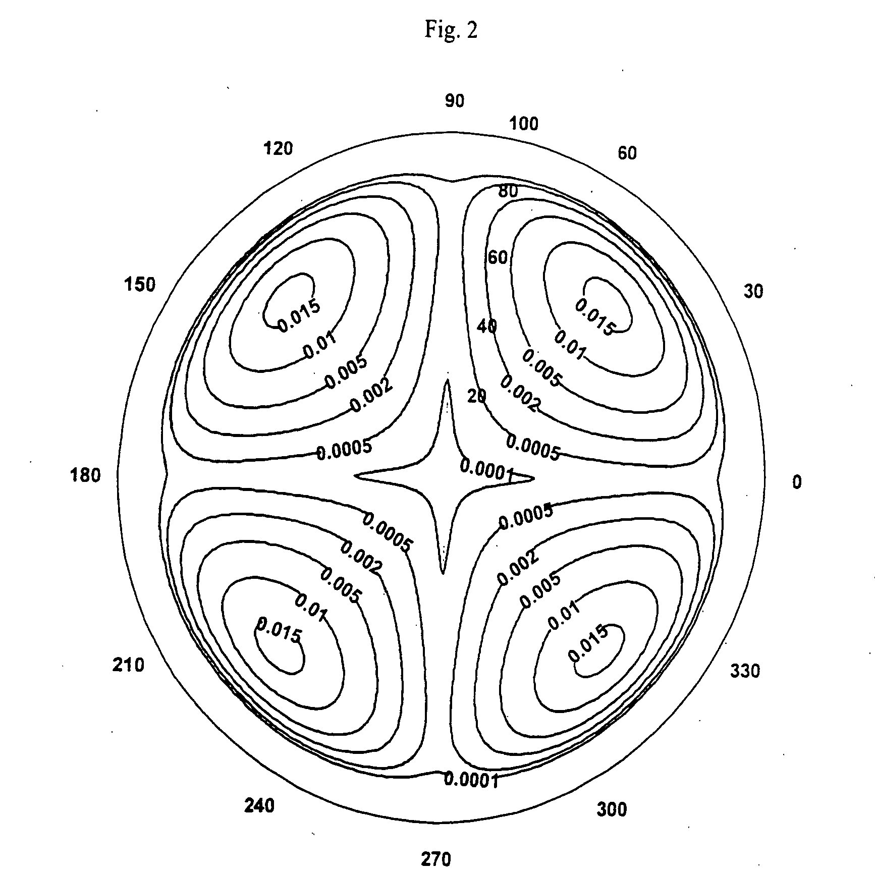
[0085]The compensation principle for the second embodiment is illustrated by the Poincaré sphere in FIG. 14. FIGS. 15A through 15C show the compensation results showing a contrast ratio that is still larger than approximately 200:1 in the approximately ±80° viewing cone.

[0086]Previous examples and embodiments have illustrated the method and apparatus of the present invention wherein the positive A-film 105 and the negative A-film 107 are laminated to the top substrate of the liquid crystal layer 103. However, the compensation films 105, 107 m...

third embodiment

[0087]FIG. 16 illustrates the structure of the multi-film compensated LCD according to the present invention. The reason that the compensation films 105, 107 can alternatively be laminated to the bottom substrate of the liquid crystal layer 103 is that after the light passes through the compensation films 105, 107, it becomes linearly polarized light along the absorption direction 110 of the top polarizer 109. As long as the liquid crystal layer 103 does not change the polarization state, the light leakage at off-state is eliminated. To do so, the alignment direction of the liquid crystal layer 103 must be parallel to the absorption direction 110 of the top polarizer 109, as shown in FIG. 16. Table 4 lists the optimized film parameters for the positive A-film 105 and the negative A-film 107.

TABLE 4RetardationFilmFilm Birefringenceof filmFilm TypeThickness (μm)Δn = ne − nodΔn (nm)Positive A-film62.50.001593.8Negative A-film58.5−0.0015−87.8

[0088]The compensation principle correspondin...


PUM

PropertyMeasurementUnit
wavelengthaaaaaaaaaa
polar angleaaaaaaaaaa

Abstract

A liquid crystal display having a positive A-film and a negative A-film between a top polarizer and a bottom polarizer to increase the viewing angle of the liquid crystal display by reducing or eliminating light leakage at voltage-off state when viewed from an oblique angle. Method of increasing the viewing angle of the liquid crystal display by reducing or eliminating light leakage at voltage-off stage when viewed from an oblique angle. The compensation is applicable to use with liquid crystal displays having a liquid crystal layer that is homogenously aligned at off-state when no voltage is applied to the liquid crystal layer, such as IPS and FFS mode liquid crystal displays.

Description

[0001]This is a Divisional of application Ser. No. 10 / 979,482 filed Nov. 2, 2004.FIELD OF THE INVENTION[0002]This invention relates to wide viewing angle liquid crystal displays and methods of increasing the viewing angles of liquid crystal displays with multi-film compensation.BACKGROUND AND PRIOR ART[0003]Liquid crystal displays (LCDs) are widely used in information displays. Due to the intrinsic optical anisotropy of liquid crystal materials, the incident light “sees” different effective birefringence when viewed from different directions. For this reason, the viewing angle of conventional LCDs is not as wide as the viewing angle for self-luminescence displays, such as the cathode-ray tube (CRT), organic light-emitting diode and the plasma display panel. In an effort to widen the viewing angle, several display modes have been disclosed using a lateral electric field to activate the liquid crystal (LC) molecules. In-plane switching (IPS) mode is disclosed in M. Oh-e, et al., “Prin...

Claims


Application Information

Patent Timeline
Patent Type & Authority Applications(United States)
IPC IPC(8): G02F1/1335
CPCG02F1/134363G02F1/133634
Inventor ZHU, XINYUWU, SHIN-TSON
Owner UNIV OF CENT FLORIDA RES FOUND INC
Why Eureka
Try Eureka