Antireflection film and display device

a display device and anti-reflection technology, applied in the field of anti-reflection film and display devices, can solve the problems of insufficient anti-reflection function of film in conical or pyramidal shape, insufficient anti-reflection function of film, and insufficient anti-reflection function in conical shape or pyramidal shape, etc., to achieve the effect of reducing the amount of light reflected to the viewer side, increasing the display device among incident light from external sources, and reducing visibility

Active Publication Date: 2008-07-03
SEMICON ENERGY LAB CO LTD
View PDF4 Cites 51 Cited by
  • Summary
  • Abstract
  • Description
  • Claims
  • Application Information

AI Technical Summary

Benefits of technology

[0027]In other words, the number of times of incidence on the antireflection film and the display device among incident light from external is increased; therefore, the amount of light transmitted through the antireflection film and the display device is increased. Thus, the amount of light reflected to a viewer side is reduced, and the cause of a reduction in visibility such as reflection can be eliminated.
[0028]When light is incident from a material with a high refractive index to a material with a low refractive index, a large difference in refractive index easily causes total reflection of light. When surfaces of the pyramidal projections are each covered with a film having a high refractive index, of light going toward the outer side of the pyramidal projections, the amount of light reflected inside the pyramidal projections at interfaces between the films and air is increased. Furthermore, the travelling direction of light inside the pyramidal projections becomes closer to a direction perpendicular to a base due to refraction of light at interfaces between the films and the pyramidal projections, and light is incident on the base (display screen); therefore, the number of times of reflection inside the pyramidal projections is decreased. Accordingly, by covering each pyramidal projection with a film having a high refractive index, the light confinement effect in the pyramidal projections is improved, and reflection to the outer side of the pyramidal projections can be reduced.
[0029]Even when the pyramidal projects

Problems solved by technology

However, with the above-described multilayer structure, a light ray, which cannot be cancelled, of the light rays reflected at the surfaces of each layer is emitted to a viewer side as reflected light.
In order to achieve mutual cancellation of light from external, it is necessary to precisely control optical characteristics of materials, thicknesses, and the like of films stacked, and it has been difficult to perform antireflection

Method used


Image

  • Antireflection film and display device
  • Antireflection film and display device
  • Antireflection film and display device

Examples


embodiment mode 1

[0071]This embodiment mode will describe an example of an antireflection film that has an antireflection function that can further reduce reflection of light from external, for the purpose of providing excellent visibility.

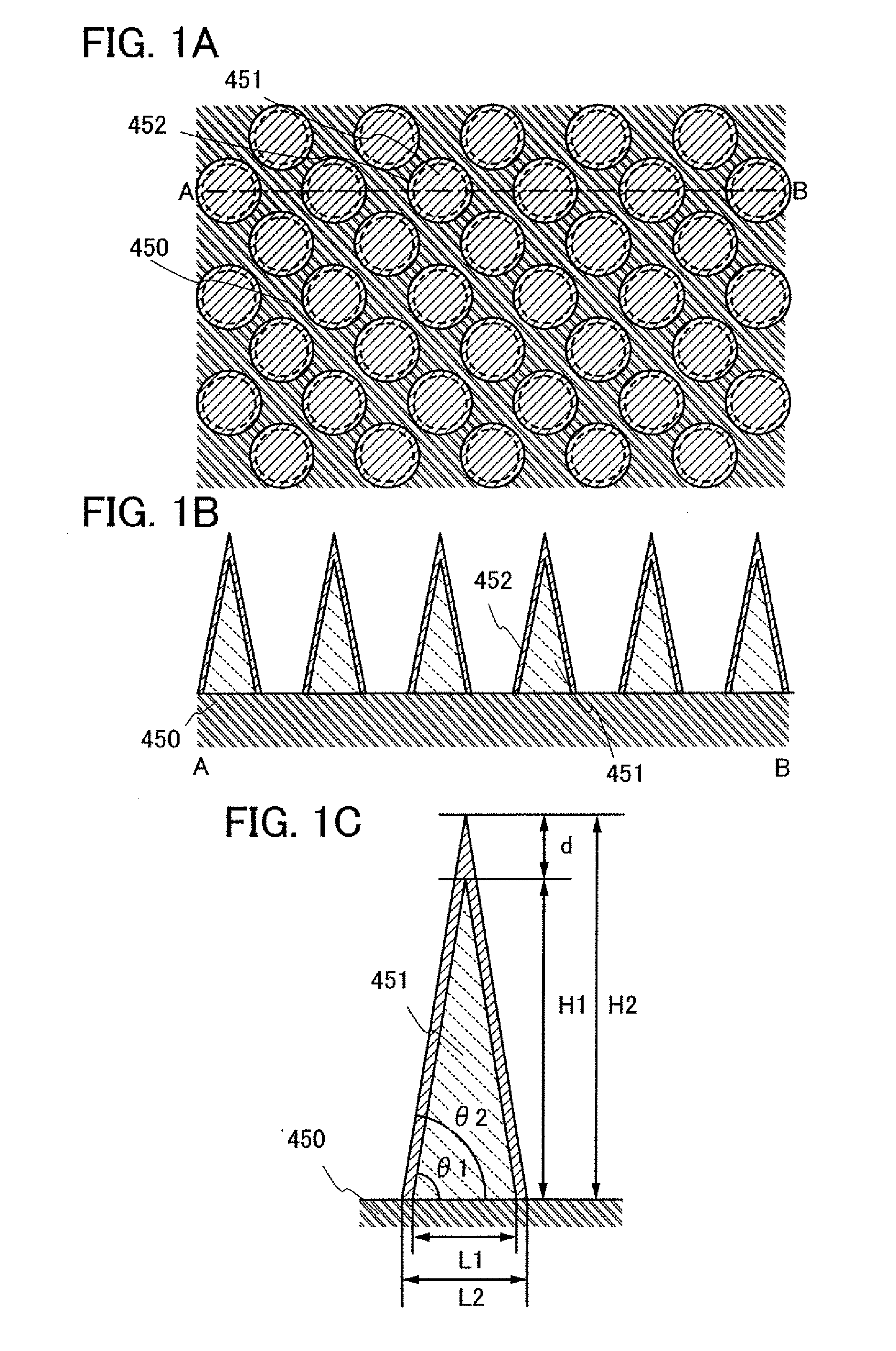
[0072]FIG. 1A is a top view of an antireflection film of the present invention and FIGS. 1B and C are cross-sectional views thereof. In FIGS. 1A and 1B, a plurality of projections 451 and films 452 are provided over a display device 450. FIG. 1A is a top view of a display device of this embodiment mode. FIG. 1B is a cross-sectional view of FIG. 1A taken along a line A-B. FIG. 1C is an enlarged view of FIG. 1B. As shown in FIGS. 1A and 1B, the projections 451 are provided to be adjacent to each other with intervals over a display screen, and there are flat surfaces (surfaces parallel to the display screen) between the projections, with respect to incident light from external.

[0073]In FIG. 1C, a height H1 of a pyramidal projection means a distance from a base to a t...

embodiment mode 2

[0107]This embodiment mode will describe an example of a display device with an antireflection function that can further reduce incident light from external, for the purpose of providing excellent visibility. More specifically, an example of a passive-matrix display device will be described.

[0108]The display device includes a first electrode layer 751a, a first electrode layer 751b, and a first electrode layer 751c which extend in a first direction; an electroluminescent layer 752 which is provided to cover the first electrode layer 751a, the first electrode layer 751b, and the first electrode layer 751c; and a second electrode layer 753a, a second electrode layer 753b, and a second electrode layer 753c which extend in a second direction perpendicular to the first direction over a substrate 759 (see FIGS. 5A and 5B). The electroluminescent layer 752 is provided between the first electrode layer 751a, the first electrode layer 751b, and the first electrode layer 751c and the second e...

embodiment mode 3

[0134]This embodiment mode describes an example of a display device having an antireflection function that can further reduce reflection of light from external, for the purpose of providing excellent visibility. This embodiment mode describes a display device having a different structure from that of Embodiment Mode 2. Specifically, this embodiment mode describes a case where the display device has an active-matrix structure.

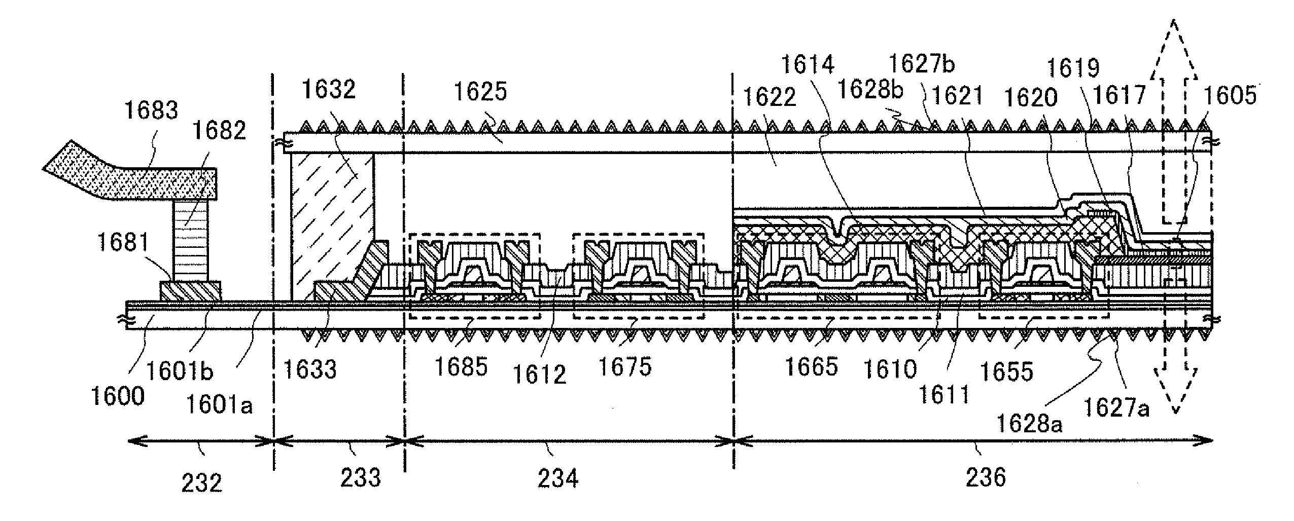
[0135]FIG. 26A is a top view of the display device, and FIG. 26B is a cross-sectional view of FIG. 26A taken along a line E-F. Although an electroluminescent layer 532, a second electrode layer 533, and an insulating layer 534 are omitted and not shown in FIG. 26A, each of them is provided as shown in FIG. 26B.

[0136]First wirings that extend in a first direction and second wirings that extend in a second direction perpendicular to the first direction are provided in matrix over a substrate 520 provided with an insulating layer 523 as a base film. One of the firs...


PUM

PropertyMeasurementUnit
Nanoscale particle sizeaaaaaaaaaa
Lightaaaaaaaaaa

Abstract

It is an object to provide a high-visibility antireflection film having an antireflection function which can further reduce reflection and a display device that has the antireflection film. A plurality of projections in a pyramidal shape (hereinafter, referred to as pyramidal projection) that are adjacent to each other are provided, and the refractive index of the projection is made to change by the physical pyramidal shape to the outer side (air side) from a surface of a display screen, so that reflection of light is prevented. In addition, the plurality of pyramidal projections are each covered with a film formed of a material having a higher refractive index than the pyramidal projections.

Description

TECHNICAL FIELD[0001]The present invention relates to an antireflection film that has an antireflection function and a display device that has the antireflection film.BACKGROUND ART[0002]In some display devices having various displays (such as a liquid crystal display or an electroluminescence display (also referred to as an EL display)), there may be a case where it becomes difficult to see a display screen due to reflection of its surroundings by surface reflection of light from external, so that visibility is decreased. This is a considerable problem particularly in an increase in size of the display device and outdoor use thereof.[0003]In order to prevent such reflection of incident light from external, a method of providing a display screen of a display device with an antireflection film has been employed. For example, there is a method of providing an anti-reflective film that has a multilayer structure of stacked layers having different refractive indices so as to be widely e...

Claims


Application Information

Patent Timeline
IPC IPC(8): G02B27/00G02F1/1335G02B1/11B32B3/14B32B7/02G02B1/118G02B1/14G09F9/00H01L51/50H05B33/02H05B33/14
CPCG02B1/118G02B5/003G02F1/133502G02B26/026G02B5/1809G02F1/133528
Inventor EGI, YUJINISHIDA, JIRONISHI, TAKESHI
Owner SEMICON ENERGY LAB CO LTD
Why Eureka
Try Eureka