Light emitting light diode light tube

a technology of light tubes and diodes, which is applied in the direction of semiconductor devices for light sources, coupling device connections, lighting and heating apparatus, etc., can solve the problems of difficult recycling and more pollution problems, and achieve the effects of reducing energy consumption, reducing pollution, and reducing lighting temperatur

Inactive Publication Date: 2008-07-03
EDISON-OPTO
View PDF13 Cites 17 Cited by
  • Summary
  • Abstract
  • Description
  • Claims
  • Application Information

AI Technical Summary

Benefits of technology

[0010]Thus, the primary object of the present invention provides a LED light tube compatible to, both in electrical and in spatial, the existed fluorescent light tube fixture, so that it can directly replace the fluorescent light tube, without refitting the fluorescent light tube fixture, to have the a...

Problems solved by technology

However, the phosphor distributed on the inner surface of the fluorescent light tube usually contains heavy metals, such as mercury, so that it is difficult to be recycled and makes more pollution ...

Method used


Image

  • Light emitting light diode light tube
  • Light emitting light diode light tube
  • Light emitting light diode light tube

Examples


first embodiment

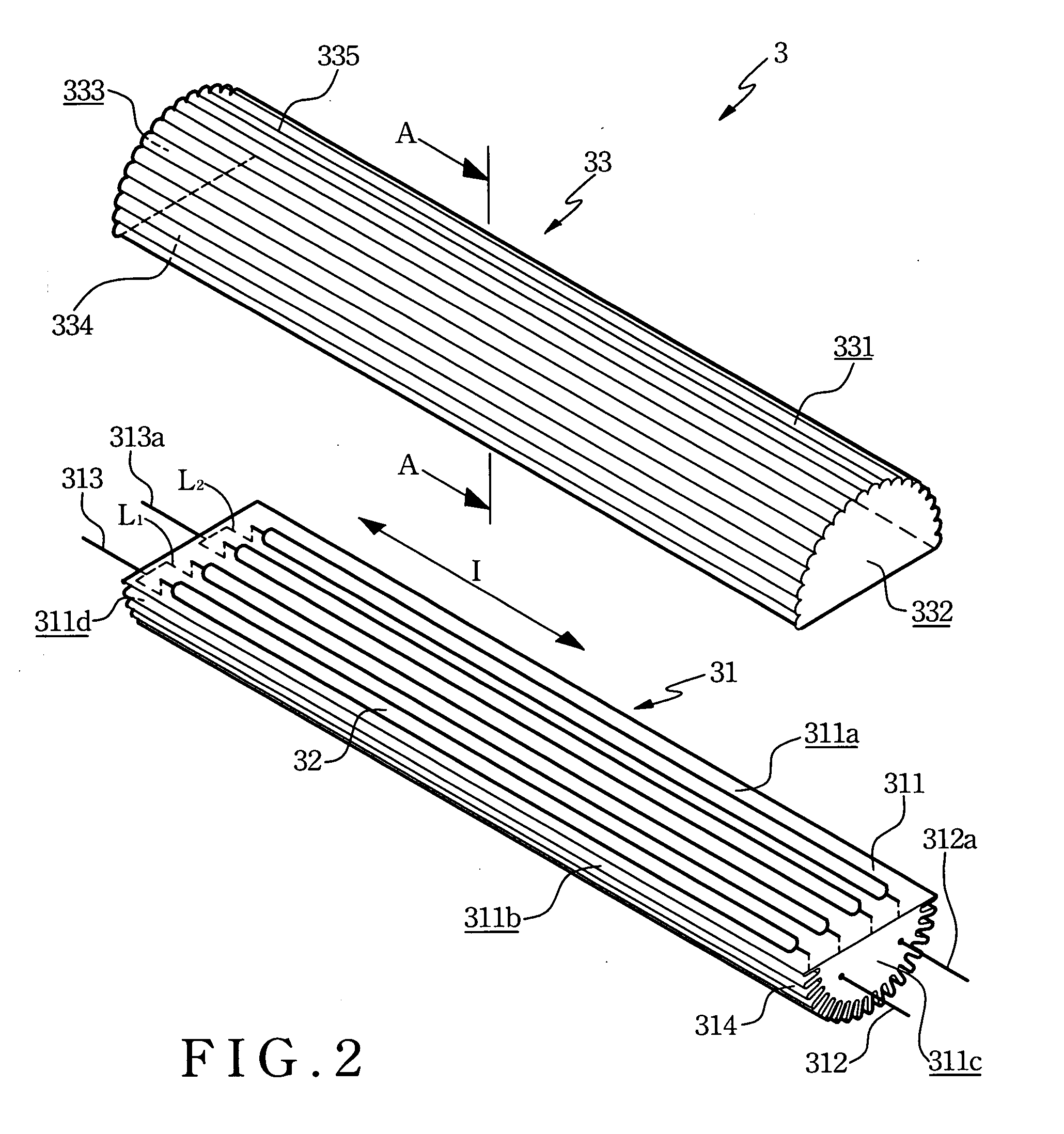
[0027]The linear-extended LEDs 32 are arranged on the arrangement surface 311a, and each one of the linear-extended LEDs 32 is parallel to the extension direction I and apart from each other. In the first embodiment, the linear-extended LEDs 32 are arranged to form two illumination circuits L1 and L2 connected with each other in a parallel connection, wherein two ends of the illumination circuits L1 are connected to the electrode contacts 312 and 313 respectively, and two ends of the illumination circuits L2 are connected to the electrode contacts 312a and 313a respectively.

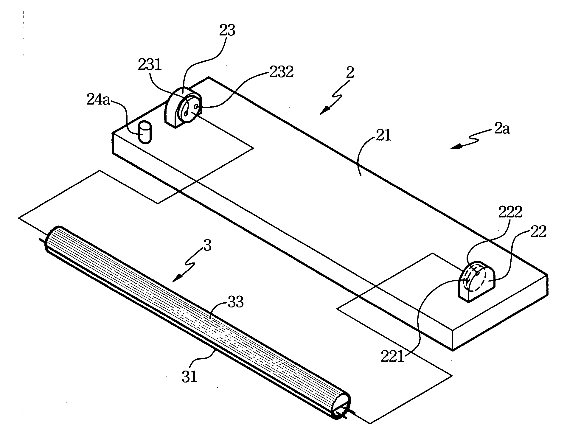
[0028]The light-transmissible shell 33 matching to the heat-dissipating base 31 can be composed of light-transmissible material, such as light-transmissible glass, acrylic, or plastic. Meanwhile, the light-transmissible shell 33 is extended along the extension direction I, and has a second peripheral surface 311, two second end-surfaces 332 and 333, an opening 334 and a plurality of grained patterns 335.

[0029]The...

second embodiment

[0035]As shown in FIG. 5, the linear-extended LEDs 32a are arranged on the arrangement surface 311a, and each one of the linear-extended LEDs 32 is vertical to the extension direction I and apart from each other. In the second embodiment, the linear-extended LEDs 32a are arranged to form two illumination circuits L1′ and L2′ connected with each other in a parallel connection, wherein two ends of the illumination circuits L1′ are connected to the electrode contacts 312 and 313 respectively, and two ends of the illumination circuits L2′ are connected to the electrode contacts 312a and 313a respectively.

[0036]For being easily manufactured and meeting specified requirements, the plurality of linear-extended LEDs 32 and 32a can be made by connecting a plurality of short linear LEDs. Furthermore, the arrangement method of the linear-extended LEDs is not limited by the disclosed two embodiments, i.e., being arranged parallel or vertical to the extension direction I. In real applications, t...


PUM


Abstract

A Light Emitting Diode (LED) light tube is applied to be directly inserted to two pairs of electrode insertion holes of a fluorescent light tube fixture to replace a fluorescent tube. The LED light tube comprises a heat-dissipating base, a plurality of linear-extend LEDs and a light-transmissible shell, wherein an arrangement surface of the heat-dissipating base is arranged with the linear-extend LEDs, a peripheral surface of the heat-dissipating base is formed with a plurality of heat-dissipating grooves, two end-surfaces of the heat-dissipating base are respectively connected a pairs of electrodes to be inserted into the electrode insertion holes, and the light-transmissible shell including an opening for covering and assembling to the arrangement surface to package the linear-extend LEDs with the heat-dissipating base.

Description

FIELD OF THE INVENTION[0001]The present invention relates to a light emitting diode (LED) light tube, and more particularly to an LED light tube applied to be assembled to a fluorescent light tube fixture for replacing a fluorescent light tube.BACKGROUND OF THE INVENTION[0002]In daily life, for exactly identifying environment and directions in the dark, illumination devices have already been a kind of indispensable tools. Most of the existed illumination devices have a light tube or a bulb served as a light source, and more familiar, the light tube or light bulb may be a fluorescent light tube, an incandescent light bulb, a halogen light tube or a halogen light bulb and so on. Among the light tubes or bulbs, the fluorescent light tube are widely used by the most people due to the reasons of the power consumption of the fluorescent light tube is one quarter of that of the incandescent light bulb, the working life of the fluorescent light tube is 5 to 10 times of that of the incandesc...

Claims


Application Information

Patent Timeline
IPC IPC(8): F21V29/00
CPCF21Y2101/02F21K9/17F21V29/77F21V29/507F21Y2103/003F21Y2103/10F21Y2115/10F21K9/275
Inventor SUN, TSUNG-TINGLIAO, HUNG-TAYEN, TZU-HSUANCHEN, PAO-SHEN
Owner EDISON-OPTO
Why Eureka
Try Eureka